41. In Delay time base oscilloscope ______ base circuit is used for main time base circuits.
Normal time base
Delay time base
Summing circuit
Deflection circuit
Answer.4. Additional time base Generator output
Explanation:
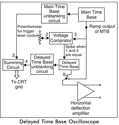
In Delay time base oscilloscope the normal time base circuit is used for main time base circuits which works the same as in other oscilloscopes.
The main time base unblanking circuit produces an unblanking pulse which is applied to CRT grid to turn on an electron beam in the CRT during the sweep time.
The ramp output of the main time base is applied to the vertical comparator and to the horizontal deflection amplifier through the switch.
The other input to the voltage comparator is derived from the potentiometer whose level is adjustable.
42. The ramp output of the main time base is applied to the _______ in the Delayed time base oscilloscope.
Main time base Unblanking circuit
Voltage Comparator
Horizontal amplifier
Both 2 and 3
Answer.4. Both 2 and 3
Explanation:
In Delay time base oscilloscope the normal time base circuit is used for main time base circuits which works the same as in other oscilloscopes.
The main time base unblanking circuit produces an unblanking pulse which is applied to CRT grid to turn on an electron beam in the CRT during the sweep time.
The ramp output of the main time base is applied to the vertical comparator and to the horizontal deflection amplifier through the switch.
The other input to the voltage comparator is derived from the potentiometer whose level is adjustable.
When the levels of ramp output of the main time base and trigger level set by potentiometer are equal then the voltage comparator produces a negative or positive output spike at that instant.
This spike triggers the delayed time base circuit.
The main time base and delayed time base unblanking circuit produces an unblanking pulse during the ramp time of the delayed time base. The unblanking pulse from these is applied to the summing circuit and then applied to the CRT.
43. When the levels of ramp output of the main time base and trigger level are equal then the voltage comparator produces ______
Negative spike Only
Positive spike Only
Both negative and Positive spike
None of the above
Answer.4. Both 2 and 3
Explanation:
In Delay time base oscilloscope the normal time base circuit is used for main time base circuits which works the same as in other oscilloscopes.
The main time base unblanking circuit produces an unblanking pulse which is applied to CRT grid to turn on an electron beam in the CRT during the sweep time.
The ramp output of the main time base is applied to the vertical comparator and to the horizontal deflection amplifier through the switch.
The other input to the voltage comparator is derived from the potentiometer whose level is adjustable.
When the levels of ramp output of the main time base and trigger level set by potentiometer are equal then the voltage comparator produces a negative or positive output spike at that instant.
This spike triggers the delayed time base circuit.
The main time base and delayed time base unblanking circuit produces an unblanking pulse during the ramp time of the delayed time base. The unblanking pulse from these is applied to the summing circuit and then applied to the CRT.
44. In Delay time base oscilloscope the delay ensure ________
Lost waveform
No Waveform is lost
High Accuracy
High Brightness
Answer.2. No Waveform is lost
Explanation:
The delay ensures that no part of the waveform gets lost, In a delayed time base oscilloscope, a variable time delay circuit is used in the basic time base circuit. This allows the triggering of sweep time after the delay time. Thus the delay time is variable. After this, the sweep is triggered for the time (. Then the portion of the waveform for the time gets expanded on the complete oscilloscope for the detailed study.
45. During Delayed time base period, the voltage applied to CRT grid is almost ______ the voltage corresponding to Main time base period.
Twice
Equal
Half
Thrice
Answer.2. No Waveform is lost
Explanation:
The input to the voltage comparator is derived from the potentiometer whose level is adjustable. The unblanking pulses from MTB and DTB are added by summing circuit and given to the CRT grid. The unblanking pulse of MTB produces a trace of uniform intensity.
But during ramp time of DTB, the addition of two pulses decides the intensity of the trace on the screen. Hence during DTB time, the voltage applied to CRT grid is almost twice than the voltage corresponding to MTB time.
46. The application of delayed time base oscillator is
Used to extend waveform
Rising and falling edges pulse measurement
Both 1 and 2
None of the above
Answer.3. Both 1 and 2
Explanation:
Applications of Delayed Time Base Oscilloscope
It is used to extend any part of the waveform on the entire screen of the oscilloscope and make it bright to analyze the desired portion of the waveform.
The rising and falling edges of the pulses are investigated with a delayed time-based oscilloscope.
If the input is pulse waveform and leading-edge is used to trigger the delay time. then lagging edge can be displayed to fill the entire oscilloscope screen.
Similarly, if the lagging edge is used to trigger the delay time then the leading edge will be displayed on the entire screen.
If the time delay is perfectly adjusted, then any portion of the waveform can be extended to fill the entire screen.
47. A digital storage oscilloscope has _________
3 modes
2 modes
4 modes
5 modes
Answer.1. 3 modes
Explanation:
The digital storage oscilloscope has 3 modes of operation:
Roll Mode: This is used to observe the fast varying signal.
Store Mode: It is called refresh mode and is most commonly used.
Hold or Save Mode: This mode is also the commonly used mode.
48. _________ stores the captured input signal in a digital mode and displays the signal without further processing.
Delay time base oscilloscope
Dual Beam Oscilloscope
Digital storage Oscilloscope
Dual Trace Oscilloscope
Answer.3. Digital storage Oscilloscope
Explanation:
A digital storage oscilloscope stores the captured input signal in a digital mode and displays the signal without further processing.
Most digital oscilloscopes can also be switched between the digital and analog modes.
Digital oscilloscopes have many desirable features.
They will be more widely used as their cost becomes more competitive or as a part of a data acquisition system.
49. In Digital storage Oscilloscope ______ method of displaying acquired waveform data without waiting for the complete waveform record.
Store Mode
Hold Mode
Role Mode
Time Mode
Answer.3. Role Mode
Explanation:
In Digital storage Oscilloscope roll mode is a method of displaying acquired waveform data without waiting for the complete waveform record.
Roll mode is the most basic mode of operation which is similar to that of a general-purpose CRO. When an input is applied, the trace is displayed on the screen. A user can use this mode to keep an eye on the waveform and its various characteristics.
50. In Digital storage Oscilloscope ______ mode is called refresh mode.
Store Mode
Hold Mode
Role Mode
Time Mode
Answer.1. Store Mode
Explanation:
In Digital storage Oscilloscope store mode is otherwise called refresh mode.
In this mode, the input initiates the trigger circuit. This initiates the memory write cycle.
The digital data is transferred to the memory when the memory is full, the write cycle stops.
Here, using DAC, the memory data is converted to analog and then displayed on the screen when the next trigger across the memory is refreshed.