Ques.11. A single-phase full-bridge voltage source inverter is operated with SPWM (sinusoidal pulse width modulation). The input DC voltage is 100 V. If the amplitude modulation index is 1, the RMS value of the fundamental component of the output voltage is
141.4 V
70.7 V
50.3 V
90.7 V
Answer.2. 70.7 V
Explanation:-
For Pulse width modulator (PWM) full-bridge rectifier the output voltage is given by
Vout fundamental = 0.707 × m × Vdc
Where
Amplitude modulation index = m = 1
Input DC voltage = Vdc = 100 V
Vout fundamental = 0.707 × 1 × 100
Vout fundamental = 70.7 V
Ques.12. In the given Wheatstone bridge, R1 = 500Ω, R3 = 200Ω. The bridge is balanced when R2 is adjusted to 125Ω. Find the resistance Rx
Rx = 100Ω
Rx = 200Ω
Rx = 50Ω
Rx = 120Ω
Answer.3. Rx = 50Ω
Explanation:-
Given
R1 = 500 Ω
R2 = 125 Ω
R3 = 200Ω
Rx = ?
According to Wheatstone bridge relation
R1 Rx = R2 R3
500 × Rx = 125 × 200
Rx = 50 Ω
Ques.13. The casual system represented by [katex]G(s) = \dfrac{9}{{({s^2} + 6s + 9)}}[/katex]
Ques.14. The average output voltage of a half controlled bridge converter is measured to be 103.53V. If the bridge is supplied from a 230V, 50 Hz sinusoidal source, the triggering angle of the thyristors in the bridge is approximately
60°
90°
120°
30°
Answer.2. 90°
Explanation:-
Given,
Average output voltage (Vo) = 103.53V
RMS voltage = 230 V
Max Voltage (Vm) = √2 × RMS voltage
Vm = 325.22 V
The average output voltage of the half-converter bridge rectifier is given by
Ques.15. Auto-transformer is used in the transmission and distribution systems
When galvanic isolation is needed.
When operator is not available
When efficiency of transformer is not critical
When the transformation ratio for voltage is small
Answer.4. When the transformation ratio for voltage is small
Explanation:-
The transformers used to step down the transmission voltage to the distribution voltage are called distribution transformers. Hence the voltage ratio of such transformers is very high. Similarly, the isolation between primary and secondary is necessary. But the autotransformers are economical only when the voltage ratio is less than 2. Similarly, the autotransformers cannot provide isolation between primary and secondary.
An autotransformer is never used as a distribution transformer because the lack of isolation can cause dangerously high-voltages in a customer’s location if the neutral opens. Autotransformers are generally used for transforming one transmission voltage to another when the ratio is 2:1 or less. They are used in a transmission substation to transform from one high-voltage to another high-voltage or from a transmission voltage to a substation-voltage. They are normally connected in wye with the neutral solidly grounded, having a delta-connected tertiary for harmonics suppression.
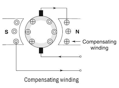
Ques.16. The compensating winding in a DC machine
Is located on the commutating poles
Is located on commutators
Is located in armature slots
Is located on pole shoes
Answer.4. Is located on pole shoes
Explanation:-
Compensating windings are used to overcome the commutation and cross-magnetization effect of armature reaction, which causes high flux density in the trailing pole tip. Also, the coil under this tip can develop an induced voltage that is high enough to cause a flashover between nearby commutator segments.
Compensating winding is connected in series with the armature winding in such a way that the current flowing in them is directly opposite to the current flowing in the armature located just below the pole faces. Half of the conductors (say left hand side of the pole) are connected in series with the other half of the conductors (on the right side of the adjacent pole).
Physically, this coil is much closer to the commutation zone in which the air temperature can be high due to the commutation process. Therefore, the compensating windings are located on pole shoes to avoid flashover.
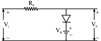
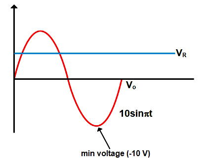
Ques.17. In the diode circuit shown in the V1=10 sin 314.159 t V and VR= 5 V. Assume the diode to be ideal. The maximum and minimum values of the output voltage (Vo) are, respectively.
+10 V and −5V
+5 V and −10V
+5 V and −5V
+10 V and −10V
Answer.2. +5V and −10V
Explanation:-
Given
Vin = 10 v
VR = 5 V
During the Positive half cycle, the diode is forward bias i.e Vin > Vrand the diode acts as a short circuit
Therefore the output voltage
Vout = Vin − Vr
Vout = 5 V (max Voltage)
During the negative half cycle, the diode is reversed biased and acts as an open circuit i.e Vin < Vr
Hence output voltage
Vout = Vin
Vout = −10 V (min voltage)
Ques.18. A load-flow program is run twice, in the second run, the previous reference bus gets changed to a PQ bus. Which one of the following statements is true?
The system losses, as well as complex bus voltages, will change.
Load flow result will remain the same in all aspects.
The system losses will change but the complex bus voltages will remain the same.
The system losses will be unchanged but the complex bus voltages will change.
Answer.4. The system losses will be unchanged but the complex bus voltages will change.
Explanation:-
The system losses are a function of system properties that are independent of choosing a type of bus. Whereas the complex bus voltage is a function of parameters that are being calculated. When a load-flow program is run twice, in the second run, the previous reference bus gets changed to PQ bus then the losses in the system remains unchanged
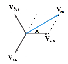
Ques.19. In a balanced acb sequence, phase a to neutral voltage is Van = 100∠20V. Line -to-line voltage Vac is given by
Vac = 100√3 ∠50V
Vac = 100√3 ∠−50V
Vac = 100 ∠50V
Vac = 100√3 ∠20V
Answer.1. Vac = 100√3 ∠50V
Explanation:-
The phase sequence is called a positive sequence or abc sequence when Van leads Vbn by 120° and Vbn leads Vcn by 120°. Line to line voltage Van leads phase voltage Va by 30º
The phase sequence is called a negative sequence or acb sequence when Van leads Vcn by 120° and Vcn leads Vbn by 120°. The line to line voltage Van lags phase voltage Va by 30º
For Negative Phase sequence ACB, the line to line voltage Vac is given as
Vac = √3Van∠−150°
Vac = √3(100V∠20°) × (1∠−150°)
Vac = 100√3∠−130°
or
Vac = 100√3∠50°
Ques.20. A 3- phase transformer bank is realized using three identical 1100/230 V, 10 kVA single-phase transformers connected in delta-delta, If one of the single-phase transformers develops a fault and is removed, the maximum load that the transformer bank in the open delta can supply is
5.77 kVA
11.54 kVA
17.32 kVA
30 kVA
Answer.3. 17.32 kVA
Explanation:-
In open delta or V-V transformer bank connection, only 86.6% or 0.866 rated capacity is available. This factor is also called as utility factor.