Ques.31. The transfer function G(S) = 1/s2 has a 0 dB crossing in its Bode magnitude plot at
100 rad/s
10 rad/s
0.1 rad/s
1 rad/s
Answer.4. 1 rad/sec
Explanation:-
Transfer function G(s) = 1/s2
In case of 0 dB crossing in Bode plot
|G(s)| = 1
|G(s)| = 1/ω2 = 1
ω = 1 rad/sec
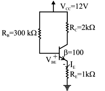
Ques.32. A BJT biasing circuit is shown in the figure. The transistor is operating in the active region with VBE = 0.7 V. The value of collector current in mA is
4.813
1.210
3.512
2.817
Answer.4. 2.817
Explanation:-
Given
VBE = 0.7 V
β = 100
Also
IE = (1 + β)IB
Applying KVL in the input loop
Vcc − (RB × IB) − VBE − [IE × RE] = 0
Vcc − (RB × IB) − VBE − [(1 + β)IB × RE] = 0
12 − (300 × IB) − 0.7 −101 × IB = 0
11.3 − 402IB = 0
IB = 0.0281 mA
Collector current IC is given by
IC = β × IB
IC = 100 × 0.0281
IC = 2.81
Ques.33. The inductance of a power transmission line increases with
Increase in diameter of the conductor
Decrease in line length
Increase in spacing between the phase conductors
Increase in load current carried by the conductor
Answer.3. Increase in spacing between the phase conductors
Hence inductance is directly proportional to the distance between the conductor. If we increase the spacing between the conductors then inductance will also increase.
Ques.34. The following are various energy sources:
Solar
Wind
Tidal
Wave
Geo-thermal
From the above energy sources, renewable energy sources are
1 and 2 only
1, 2, and 4
1, 2, and 3
All the energy sources mentioned above
Answer.D. All the energy sources mentioned above
Explanation:-
Resources that can be renewed by nature again and again so that their supply is not adversely affected by the rate of their consumption are called renewable sources of energy. E.g are solar, tidal, wind, geothermal, etc.
Ques.35. An ideal air-core coil has an inductance of 2 mH. The number of turns of the coil is doubled and its length is halved. Assuming that the inner cross-sectional area of the core remains constant the new inductance of this altered air-core coil is
Ques.36. An electrostatic field is given by [katex]E = \left( {\dfrac{x}{2} + 2y} \right)\widehat i + 2x\widehat j[/katex] V / m . Find the work done in moving a point charge Q = −20 μC from the origin to (4,0,0) m. [katex](\widehat i,\widehat j)[/katex] are the unit vectors along x,y-axis.
Ques.37. The effective charge flowing through a wire is given by, q = 5t sin 4πt mC. Calculate the instantaneous current flowing at time t=0.5 s.
31.4 mA
0 A
2.5 mA
3.14 mA
Answer.1. 31.4 mA
Explanation:-
Charge flow q = 5t sin 4πt
The rate of flow of electrical charge is given by
I = dq/dt
I = d[5t sin 4πt]/dt
I = [5 sin(4πt) + 5t × 4π cos(4πt)]
t = 0.5 sec
I = [5 sin(2π) + 20π × 0.5 cos(2π)]
I = [0 + 10π × 1]
I = 10π = 10 × 3.14
I = 31.4 mA
Ques.38. A circuit with a resistor, inductor, and capacitor in series has a resonant frequency of fo Hz. If all the component values are now doubled, the new resonant frequency is
2fo
fo/2
fo/4
fo
Answer.2. fo/2
Explanation:-
The resonant frequency for series R-L-C circuit is given by
Ques.39. The inductance of a certain moving-iron ammeter is expressed as [katex]L = 10 + 3\theta – \dfrac{{{\theta ^2}}}{4}\mu H[/katex] where θ is the deflection in radians from the zero position. The control spring torque is 25 × 106 Nm/radian. The deflection of the pointer in radians, when the meter carries a current of 5 A RMS is
Ques.40. The open-loop gain-bandwidth product of an op-amp is given as 10,000 Hz. The op-amp is used in an inverting amplifier as shown in the figure. The bandwidth of the inverting amplifier is