Ques 11. Current rating is not necessary in the case of
Switch
Isolators✔
Switch and Isolators
Circuit Breakers
An isolator is a off-load device which is employed only for isolating the circuit when the current has already been interrupted. They ensure that the current is not switched into the circuit until everything is in order. They do not have any specified current breaking capacity or current making capacity.
Ques 12. Consider the following statements
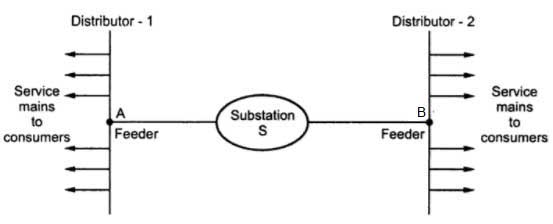
Statement 1: Electricity is distributed from a single point in a radial distribution system
Statement B: There is less fluctuation in supply at the consumer’s terminal.
Which of the following is correct?
A and B are true but B is not the correct explanation of A✔
A is true but B is false
B is true but A is false
A and B are true and B is the correct explanation of A
When the distributor is connected to the substation at only one end only with the help of the feeder then this system is called a Radial system.
In the radial system, if the fault occurs on the feeder or distributor then all the consumers get affected.
The system is useful only when the generation at the low voltage level and the substation are loaded at the center of the load.
Consumers are dependent on a single feeder and a single distributor. Therefore, any fault on the feeder or distributor cuts off supply to the consumers who are on the side of the fault away from the substation.
The consumers at the distant end of the distributor would be subjected to serious voltage fluctuations when the load on the distributor changes. Due to these limitations, this system is used for short distances only.
The RIng main system is very reliable as each distributor is fed via *two feeders. In the event of a fault on any section of the feeder, the continuity of supply is maintained. Hence there are fewer voltage fluctuations at consumer terminals.
Hence both the statement is individually correct but statement A is for Radial System and Statement B is for the Ring main system
Ques 13. When the sender’s end voltage is more the power transmitted will be
Maximum✔
Unpredictable
Zero
Minimum
Voltage regulation of transmission line is given as
VR = VS – VR
When the VS >> VR the power transfer is maximum
In case the sending end voltage is not more than the receiving end voltage then the current start flowing in the reverse direction i.e from receiving end to sending end this phenomenon is called the Ferranti effect.
This occurs when the line is energized, but there is a very light load or the load is disconnected.
Ques 14. Critical Resistance in a DC generator is increased by
Increasing Speed✔
Decreasing Speed
Continuously fluctuating field resistance
Keeping field resistance constant
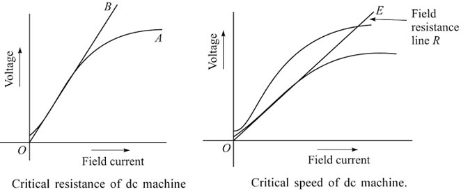
Critical Resistance and Critical Speed of the DC Machine
Critical field resistance is a term that is associated with a shunt DC generator. If the field resistance of the dc shunt machine is gradually increased, then a condition wi appear when the resistance line OB will coincide with the linear portion of the magnetization curve (i.e. open-circuit characteristic). After that, if the resistance of the field is increased, no voltage will be built up for the dc machine. The resistance for this line OB is termed the critical resistance.
Thus we can define critical resistance as that resistance of the field circuit at a given speed at which generator just excites and starts voltage building while beyond this value generator fails to excite.
Suppose the field resistance line of a dc generator is OE and the field resistance is R. We know that the induced voltage of a dc machine depends on speed i.e E ∝ N. If the speed of the dc machine varies, the open-circuit characteristic will vary. So a condition may come when the field resistance line OE is the critical resistance line for a particular OCC being formed due to the change in speed. This speed at which the machine just excites for the given field circuit resistance is called the critical speed of a shunt generator.
Ques 15. Self-excitation of a series generator
Is possible only when load current is zero
Is possible only when load current is not zero✔
Is not possible
Is independent of the load current
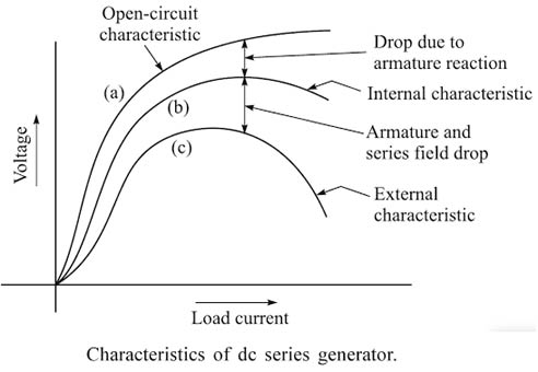
Characteristics of DC Series Generator
In the case of a series generator
Ia = Ise = IL
Where Ia = Armature current
Ise = Series field current
IL = Load current
When the load current is zero, the generated and terminal armature voltages are the same, both being due to the residual magnetic field. As load current increases, Ise increases. The flux Φ is directly proportional to Ise. So flux also increases. The induced e.m.f. E is proportional to flux hence induced e.m.f. also increases. Thus the internal characteristics are of increasing nature.
The load current produces two voltage drops as shown in Figure thus limiting the voltage across the load. The generated voltage is also reduced by the effects of armature reaction. As a result of voltage drops tending to decrease the generated voltage and the magnetizing current tending to increase the generated voltage, a maximum voltage is produced where the buildup ceases. At this point, the voltage drops of the series field and the armature, as well as the voltage drop due to the armature reaction, exactly counterbalance the increased flux produced in the series field, and the terminal voltage, therefore, remains constant.
Any further increase in load beyond the maximum voltage point produces a sharply drooping characteristic as shown in Figure. The reason is that the increased voltage drops and the increased armature reaction decrease the load voltage a much faster than the increase in generated voltage taking place by the increased load current.
The conditions for voltage build up in self-excited generators are:
Residual magnetism must be present
Field winding should be properly connected so that field current strengthens the residual magnetism.
The resistance of the field should be less than the critical resistance
The speed of the machine should be higher than the critical speed.
For series, generator load should be connected and resistance of load should be less than critical resistance.
Ques16. If a DC series motor is made to run on AC supply. It will
Have no effect on efficiency
Spark in excess but will not affect the efficiency
Spark excessively and have poor efficiency✔
Have poor efficiency
Series Connection:
In DC machine, T = kφi where k = number of poles and the number of turns in the winding. Φ = flux per pole i = current.
If saturation of core is neglected, then Flux is proportional to field current.
So Torque= k *field current*armature current.
For DC series machine, Armature current = Field Current, Therefore, Torque = k × Ia2
If we apply AC then both, during positive as well as negative half cycle, torque is positive from above relation. So, torque is unidirectional, but due to AC, it will be pulsating.
Parallel connection:
But, In the case of parallel connection, it won’t rotate at all and will start humming and will create vibrations, as a torque produced by positive and negative cycle will cancel out each other. D.C. motor will be heated up.
Ques 17. The rotor reactance per phase, in an induction motor, is:
Directly proportional to the square of slip
Directly proportional to slip✔
Inversely proportional to the square of slip
Inversely proportional to the slip
A rotor reactance is due to the circuit inductance formed by the cage conductors embedded in iron. Since reactance is directly proportional to frequency hence the rotor will vary as the slip changes.
Rotor reactance at any speed = standstill reactance x slip.
Ques 18. The ratio of voltage Drop across a conductor to the conductor’s resistance is:
Electric Field
Current✔
Magnetic flux
Magnetic Field
The Proportional relationship between Voltage (V) and Current(I) always gives us a constant ratio which we call resistance or R
And this Ohm’s Law :
R=V/I
I= V/R
Ques 19. The impedance of a series resonant circuit is:
Minimum✔
Zero
Infinite
Maximum
The total impedance of the series LCR circuit is given as
Z = R + j (X1 – X²)
where X1 is inductive reactance
and X2 is capacitive reactance.
At a particular frequency (resonant frequency), we find that X1=X2 because the resonance of a series RLC circuit occurs when the inductive and capacitive reactances are equal in magnitude but cancel each other because they are 180 degrees apart in phase.
Ques 20. Which of the following does not increase when the load on the squirrel cage induction motor is increased from No-load to full load?
Magnetizing components of stator exciting current✔
Torque developed by the motor (up to the magnitude of applied torque)
Stator power factor
Slip
Basically, there are three current components in the induction motor: Magnetizing current, loss current, and load current. Since the magnetizing current is dependent on the design of the stator and stator voltage, it is constant i.e it is independent of the load.
A low magnetizing current indicates low iron loss, while a high magnetizing current indicates an increase in iron loss and a resultant reduction in operating efficiency.
The magnetizing current causes a reduction in the power factor. Hence by reducing the supply voltage, the power factor can be improved.