A Hall effect sensor is a transducer that produces its output voltage in response to changes in magnetic fields. Applications of Hall effect sensors are
Determinationof semiconductor type: The Hall coefficient is negative for a p-type semiconductor and positive for a p-type semiconductor. Therefore, the sign of the Hall coefficient can be used to determine whether a given semiconductor is n- or p-type.
Determination of carrier mobility: By measuring the Hall coefficient and conductivity of the semiconductor, carrier mobility can be determined.
Determination of carrier concentration: By measuring the Hall coefficient the carrier concentration in a semiconductor can be determined.
Measurement of magnetic fields: Hall voltage is proportional to the magnetic field intensity, for a given current through the sample. Therefore, one of the important applications of the Hall effect consists in measuring magnetic fields. Knowing the parameters of the Hall probe, and applied current, we can determine the intensity of the magnetic field.
Miscellaneous applications: Hall sensors are used for proximity switching, positioning, speed detection, and current sensing application.
Ques.132. Three coils, each having a resistance of 10 ohms and an impedance of 0.02 H, are connected in star across a 440 V, 50 Hz, three-phase supply. What will be the line current?
25 A
25.4 A
0 A
25.51 A✓
Given
Inductance L = 0.02 H
Resistance R = 10 Ω
Line voltage VL = 440 V
Inductive Reactance XL = 2πfL
Frequency f = 50 Hz
XL = 2 × π × 50 × 0.02
XL = 6.28 Ω
Impedance per phase ZP
ZP = √(R2 + X2L)
ZP = √(102 + 6.282)
ZP = 11.8
In star connected system the phase voltage is
VP = VL/√3 = 440/√3 = 254.03 V
IP = Vp/Zp
IP = 254.03/11.8
IP = 21.52A
In star connected system the phase current is equal to the line current.
IP = IL = 21.52A
Ques.133. In a three-phase load, ____ difference impedance are connected together in a star or delta fashion.
Six
Zero
Three✓
One
The load can be connected in two ways,
i) Star connection
ii) Delta connection
The three-phase load is nothing but three different impedances connected together in star or delta fashion
1) Star connected load: There are three different impedances and are connected such that one end of each is connected together and the other three are connected to supply terminals R-Y-B as shown in the fig
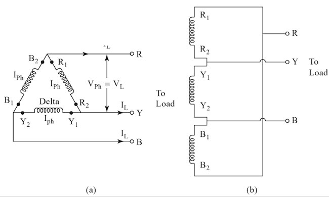
Delta Connection
The delta connection is formed by connecting the end of one winding to the starting end of the other and connections are continued to form a closed loop. In this case, the current flowing through each line conductor is called line current IL and the current flowing through each phase winding is called phase current, Iph.
However, the phase voltage is the same as the line voltage in a delta connection. The supply terminals are taken out from the three junction points. The delta connection of windings has been shown in Fig.
Key Point: The voltage across any branch of the three-phase load i.e across Zph1, Zph2 or Zph3 is called phase voltage and the current passing through any branch of the three-phase loads is called phase current.
Ques.134. A device capable of detecting voltage, current, and the angle between the voltage and the current to provide power reading directly in watts is known as
Ammeter
Wattmeter✓
Power Factor
Voltmeter
A wattmeter is an instrument with a potential coil and a current coil so arranged that its deflection is proportional to V.I.cosφ, where V is the voltage (RMS value) applied across the potential coil, I is the current (RMS value) passing through the current coil, and φ is the angle between V and I.
By inserting such a single-phase wattmeter to measure the average real power in each phase (with its current coil in series with one phase of the load and its potential coil across the phase of the load), the total real power in a three-phase system can be determined by the sum of the wattmeter readings.
Hence a wattmeter is an instrument used to measure the measure active power and phase angle supplied to a circuit. Induction type Wattmeter is used to measure A.C. power only in contrast to dynamometer wattmeter which can be used to measure D.C. as well as A.C. power.
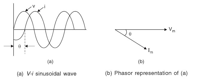
Ques.135. When the two quantities are in the quadrature, the phase angle between them will be______
90°✓
45°
135°
60°
When the phase difference between two waves is 90° (it may be = + 90° or – 90°), then the waves are said to be in ‘Phase quadrature’.
If the phase angle is equal to π they are in antiphase or phase opposition.
Ques.136. The two-wattmeters method is used for the measurement of power in a three-phase balanced system, supplied from a 415 V, three-phase, 50 Hz supply. If the reading on both wattmeters is 8.5 kW, calculate the total power consumed.
2.36 kW
20 kW
22.2 kW
17 kW✓
As given in the above question
W1 = 8.5 kW
W2 = 8.5 kW
VL = 415 V
Total power consumed
W = W1 + W2 = 8.5 + 8.5 = 17kW = 17000W
Ques.137. A three-phase star-connected balance load of (4 − j3) Ω per phase is connected across a three-phase 50 Hz, 400V AC supply. Determine current drawn from the supply.
46.188 A✓
20.23 A
50.54 A
50.522 A
Given
Voltage = 400 V
Zph = (4 − j3)
|Zph| = (42 + 32)1/2
|Zph| = 5Ω
also
VP = VL/√3 = 400/√3
VP = 230V
IP = Vp/Zp
IP = 230.94/5
IP = 46.18A
In star connection, the line voltage is equal to the phase voltage
IP = IL = 46.18A
Ques.138. Alternating quantities of _____ frequencies can be represented in the same phasor diagram.
Different
Negative
Same✓
Multiple
A quantity is called phasor if it satisfies the two criteria
it varies sinusoidally with time
It can be represented by the projection of a rotating vector
Alternating quantities of same frequencies can be represented in the same phasor diagram.
A phasor is a complex number representing a sinusoidal function whose amplitude (A), angular frequency (ω), and initial phase (θ) are time-invariant.
In practice, when we solve any A.C circuit, more than one sinusoidal quantity is involved. All these quantities can be represented on the same diagram by phasors inclined at different angles to the reference phasor. If all the phasors have the same frequency, they will rotate with the same angular speed ω.
The phase will change with time, indicating that their magnitude changes with time but the phase difference between any two phasors will remain the same with time. The relation position of phasors (i.e. phasor difference) is important for ac calculations. The graphical representation of the phasors of sinusoidal quantities at the same frequency with proper phase relationships is called a phasor diagram.
Ques.139. A thermocouple is used for measurement of____
Pressure
Temperature✓
Density
Humidity
A thermocouple is a device for the measurement of temperature. Its operation is based on the findings of the Seebeck effect. According to the Seebeck effect, a small electric current will flow in a closed circuit composed of two dissimilar metallic conductors when their junctions are kept at different temperatures.
The electromotive force, emf, produced under these conditions is known as the Seebeck effect. The pair of conductors or thermocouple elements, which constitutes the thermoelectric circuit is called a thermocouple.
Simply stated, a thermocouple is a device that converts thermal energy to electric energy. The amount of electric energy produced can be used to measure temperature.
Ques.140. The energy stored in a capacitor is given by___
C2V
CV2/2✓
C2V/2
CV
The capacitance of a capacitor is defined as the measure of the charge stored by the capacitor per unit voltage; C = Q/V
Hence Q = CV
Energy stored In the charged capacitor
When a capacitor is charged by a voltage source (say a battery) it stores the electric energy. If C = capacitance of the capacitor; Q = charge on capacitor and V is the potential difference across capacitor then the energy stored in capacitor is given by