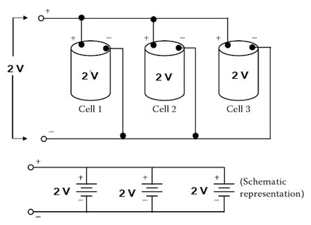
Ques.51. The output voltage, when five cells of 2V each are connected in parallel, will be___
0.4 V
1 V
2.5 V
2 V✓
In the parallel connection, all of the positive electrodes are connected to one line, and all of the negative electrodes are connected to the other. Any point on the positive side can serve as the positive terminal of the battery and any point on the negative side can be the negative terminal. Hence the potential difference across each cell remains the same The total voltage output of a battery of five parallel cells is the same as that for a single cell i.e 2V.
Ques.52. For balanced lagging power factor, according to two wattmeter method,
W1 = VLILcos(30 − φ)
W2 = VLILcos(30 + φ)
The total reactive volt-ampere Q is given by
Q = 0
Q = √3VLILsinφ
Q = 1
Q = VLILsinφ✓
Reactive power is the electrical power that oscillates between the magnetic field of an inductor and the electric field of the capacitor. Reactive power exists in an AC circuit when the current and voltage are not in phase. Reactive Power Cannot Converts to non-electrical power e.g. heat, light & torque.
Reactive power is also referred to as an imaginary power. Reactive power is the useful concept in power system because the system voltage is affected by the reactive power. The reactive power taken by an inductor is positive while the reactive power taken by the capacitor is negative.
Proving:
We know that the average power or real power dissipated is
Pavg = VI CosΦ———(1)
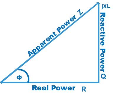
The power triangle or Impedance triangle of the AC circuit is shown Below
By Ohm’s Law, the impedance of the circuit is given as
Z = V/I
V = IZ
Putting the value of cosΦ and V in equation 1
The above equation indicates the average power dissipated in a resistive circuit.
Now let us assume a circuit consisting of a pure inductor, then the power in the inductor is given as
P = IVL
= IL(di/dt)
Where I = Im sin(ωt + Φ)
then
P = I2m sin(ωt + Φ) Lω Cos(ωt + Φ)
P = I2 ωLsin2(ωt + Φ)
From the above equation, we can say that the average power delivered to the circuit is zero. This is called reactive power. It is expressed in volt-amperes reactive (VAR).
P = I2XL VAR ————2
From Impedance figure
SinΦ = XL/Z = XL = ZsinΦ
Putting the value of XL in equation 2
P = I2 ZsinΦ
P = (IZ) IsinΦ
P = V I SinΦ
In two wattmeter method, the reactive power is given by
Q = VLILsinφ
Ques.53. The two-wattmeter method is used to measure the power of a three-phase balanced system powered by a 415 V, three-phase, and 50 Hz power supply. If the reading on both wattmeters is 8.5 kW, calculate the line current.
23.65 A✓
23.65 V
2.365 V
2.365 A
As given in the above question
W1 = 8.5 kW
W2 = 8.5 kW
VL = 415 V
The power factor of the two wattmeters is
tanØ = √3[(W1 – W2) / (W1 + W2)]
tanØ = √3[(8.5 – 8.5) ⁄ (8.5 + 8.5)]
Φ = 0°
Power factor = cosφ = cos0° = 1
Total power
W = W1 + W2 = 8.5 + 8.5 = 17kW = 17000W
Active power in wattmeter
W = √3.VL.IL.cosφ
17000 = √3 × 415 × IL × 1
IL = 23.67 A
Ques.54. The unit of electric flux density is
Hm2
Tesla
C/m2✓
Cm2
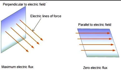
Electric flux density:- A measure of the strength of an electric field generated by a free electric charge, corresponding to the number of electric lines of force passing through a given area. It is equal to the elective field strength multiplied by the permittivity of the material through which the electric field extends. It is measured in coulombs per square meter. Also called electric displacement.
D = εoE c/m2
where
εo = Permittivity of free space F/m
E = Electric field strength
Electric flux density can also be defined as the amount of flux passing through a defined area A that is perpendicular to the direction of the flux
D = Q/A c/m2
Ques.55. Which of the following condition is unlikely to occur in a voltage surge?
Damage to insulation
Damage to electronic components
Tripping of sensitive equipment
Flicker in incandescent lamps✓
Voltage Surges
A voltage surge is a temporary rise in voltage amplitude of a power-line. Unlike short voltage spikes, a voltage surge is defined as lasting at least one-half cycle (1/120 second). In many cases, this type of disturbance is caused by switching off high-powered electric motors or other electrical equipment (causing a reduced current load and the corresponding increase in voltage).
Even something as commonplace as an air-conditioning system can momentarily boost the line voltage thousands of volts. Almost everyone has witnessed the short change in brightness of lights coinciding with the activity of nearby electrical motors (such as air conditioners, refrigerators, tools). This is caused by an uncontrolled voltage and current surge and the matching increase in power dissipation in the light resulting in a momentary brighter light.
Ques.56. The frequency of the DC system in India is___
60 Hz
50 Hz
0 Hz✓
110 Hz
Frequency is the no. of cycles per second. It means the no.of cycles obtained during a given time period. It means the DC supply must alternate between positive and negative axes in the waveform to complete full cycles. In DC, the current-time graph is a straight line. So, no ripples. So, no cycles. Hence, no frequency.
Ques.57. The capacitance of the parallel plate capacitor is given by____
C = εrd/A
C = εod/A
C = εrA/d
C = εoA/d✓
The capacitance C of a capacitor is the ratio of the magnitude of the charge on either conductor (plate) to the magnitude of the potential c^lif^rerence between the conductors (plates).
C = Q/V
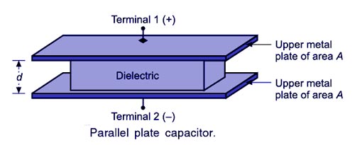
THE PARALLEL-PLATE CAPACITOR
The figure shows the structure of a parallel plate capacitor. It is made up of two parallel plates of the area of cross-section A, kept in an insulating medium and separated from each other by a distance of d metros. Then, if the two plates are applied with a potential, one of the plates will be positively charged and the other negatively charged. Let the charge on the plates be given by Q coulombs.
The capacitance of a device depends on the geometric arrangement of the conductors. The capacitance of a parallel-plate capacitor with plates separated air can be easily calculated from three facts.
The magnitude of the electric field between two plates is given E = σ/εo, where σ is the magnitude of the charge per unit area on each plate and εο = Permittivity of free space = 8.85 × 10⁻¹²
Second, the potential difference between the two plates is ΔV = Ed, where d is the distance between the plates.
Third, the charge one plate is given by q = σA, where A is the area of the plate. Substituting the three facts into the definition of capacitance gives the desired result:
Ques.58. What is the expression for current in the R-C circuit?
i = (V/R)e−t/RC✓
i = (V/R) − e(−t/RC)
i = (V/R) − e(t/RC)
None of the above
The transient response of current in RC circuit
i = (V/R)e−t/RC
Ques.59. For a star-connected three-phase AC circuit, the:
Line current is equal to three times the phase current
Phase current is equal to the line current✓
Phase current is three times the line current
Line current is equal to the phase voltage
In star connected load the phase voltage between the neutral point and any one of the line connections is 1/√3 × VL of the line voltage.
Therefore the line voltage is √3 times the phase voltage.
i.e VL = √3Vph
In star connection, the line current is equal to the phase current.
IL = Iph
Ques.60. The two-wattmeter method is used for the measurement of the total power in a balanced circuit. Current is supplied from a 415V, 50 Hz, three-phase, balanced supply. Calculate the total power if both the reading are 4.5 kW each.


 = {I^2}R\ watt")
d}}\\\\C = {\varepsilon _o}\dfrac{A}{d}\end{array}")