Ques.102. Synchronizing power of a synchronous machine is:-
Inversely proportional to the synchronous reactance✓
Equal to the synchronous reactance
Directly proportional to the synchronous reactance
Greater than the synchronous reactance
Nowadays, almost all alternators are connected it parallel with other alternators. The satisfactory parallel operation of alternators depends upon the synchronizing power. If the synchronizing power is higher, the higher is the capability of the system to synchronism.
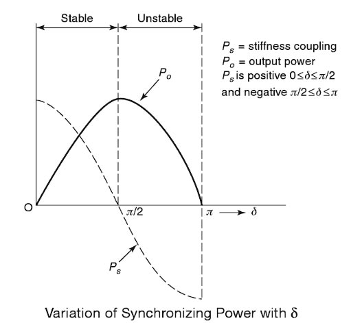
The variation of synchronous power with the change of load angle is called the synchronizing power. It exists only during the transient state, i.e. whenever there is a sudden disturbance in load (or steady-state operating conditions). Once the steady state is reached, the synchronizing power reduces to zero.
If an alternator transfers power to an infinite bus at a steady-state power angle δoand a sudden transient disturbance due to increase in load will occur the rotor of the alternator will accelerate and at a load angle δo + dδ, the alternator supplies new power P + dP. Therefore, the operating point shifts to a new line. The steady-state power input remains unchanged. Therefore, the additional load decreases the speed of the machine and hence the alternator comes back to the steady-state position. Similarly, due to sudden transient, if the rotor retards, the load angle will decrease. The operating point will shift to a new line and the load on the machine becomes P – dP. Once again the input to the machine remains unaltered, therefore, the rotor is accelerated due to the reduction in load. Hence, the machine comes back to synchronism. Therefore, we can conclude that the effectiveness of this correction action depends upon the change in power transfer for a given change in load angle
The synchronizing power flows from or to the bus in order to maintain the relative velocity between an interacting stator and rotor field, zero, once the equality is reached, the synchronizing power vanishes.
The synchronizing power coefficient, which is defined by the rate at which synchronous power varies with load angle (S) gives a measure of effectiveness. The synchronizing power coefficient is also called stiffness of coupling, rigidity factor or stability factor. It is denoted by Psyn.
The synchronizing power of the synchronous machine is given as
Where
V = supply Voltage
Eb = Back E.M.F
Xs = Synchronous Reactance
Hence from the above expression, it is clear that synchronizing power is inversely proportional to the synchronous reactance.
Ques.103. Amount of current flowing in the circuit 12V battery source and the single resistor of resistance 24K
50A
288 kA
2 kA
50 mA✓
Given
V = 12 V
R = 24 K = 24 × 103 Ω
From the ohms Law
I = V/R
I = 12/24 × 103
I = 0.5 × 10⁻³
I = 50mA
Ques.104. Amount of electricity consumed by a 100 Watt bulb (in the ON state for 10 Hours) is:-
100 Watts per hour
100 Watts
1 kWh = 1 unit of electricity✓
100 Watts
Given
Power = 100 Watt
Time = 10 Hour
Energy consumed
E = Power × Time
E =100 × 10 = 1 kWh = 1unit
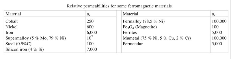
Ques.105. Value of relative permeability for a ferromagnetic material is:-
More than one
More than 100 or 1000✓
Less than one
None of these
Ferromagnetic materials the most useful magnetic materials. These derive their name from iron (Ferrum) as the most common of the ferromagnetic materials. The relative permeability of ferromagnetic materials is much larger than 1 and can be in the thousands or higher. Some typical ferromagnetic materials are iron, cobalt, and nickel.
Ferromagnetic materials tend to magnetize in the direction of the magnetic field and some of them retain this magnetized lion after the external magnetic field has been removed. When they do so, and the magnetization is permanently retained, the material becomes a permanent magnet.
An additional important property of ferromagnetic materials is the dependence o magnetization on the level of the external field. Thus, magnetization in ferromagnetic materials is a nonlinear process.
Ques.106. Among this alternative, PIV rating of which diode is lower than that of equivalent vacuum diode?
PN junction Diode
Crystal Diode✓
Tunnel Diode
Small single Diode
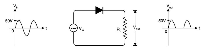
Peak inverse voltage,VR:– Peak inverse voltage is the peak voltage which appears across the diode when it is not conducting. In other words, it is the maximum voltage that the diode can with stand under reverse bias condition.
A PN junction is known as a semiconductor diode or crystal diode.
A PN-junction diode is formed when a p-type semiconductor is fused to an n-type semiconductor creating a potential barrier voltage across the diode junction.
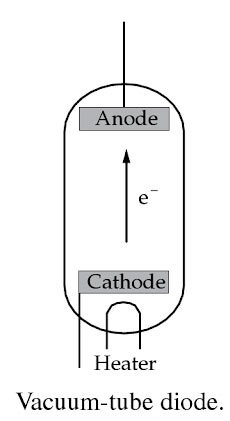
Vacuum-tube diode, the simplest type of vacuum tube consisting of cathode and anode. Since electrons can flow only from the cathode to anode, the vacuum-tube diode serves as the rectifier. Vaccum diode is not a semiconductor diode
The reverse electric field in a diode manifests over atomic distances while in a vacuum tube it manifests itself over centimeters between plates hence in the former a small field is acting over a small distance while in the latter a larger field is necessary due to the inverse relationship of distance to electric field strength.
The vacuum diode is best suited for use in rectifiers delivering several hundred volts or higher at currents of the order of milliamperes to hundreds of milliamperes.
Even small receiving-type tubes have peak inverse voltage ratings in the region of 1500 volts, and tubes with inverse voltage ratings in the range frown 50,000 to 150,000 volts are not uncommon whereas crystal diodes are designed to breakdown at the specific reverse voltage in order to avoid any damage), PIV rating of a generic “rectifier” diode is at least 50 volts at room temperature.
Ques.107. The output voltage of the regulated power supply can be altered by changing which of the following?
Injected voltage
Load current
Temperature
All of these✓
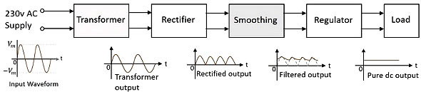
A dc power supply that maintains the output voltage constant irrespective of fluctuations of ac mains voltage or variations of the load is known as the regulated dc power supply.
A regulated power supply consists of an ordinary power supply and a voltage regulating device. The figure shows the block diagram of a regulated power supply.
A voltage regulator maintains a constant dc output voltage irrespective of the changes in either A.C input voltage or the load current. For example, the output voltage should be maintained within ±1% of the specified voltage. An ideal regulated power supply is an electronic circuit, which is able to provide a constant output voltage during the following conditions:
1. Change in input voltage
2. Change in load current due to the variation of load
3. Change in temperature
The load current (IL): An ideal power supply maintains a constant voltage at its output terminals, inspites of changes in load current. But practically in a power supply without the regulator, the load voltage decreases as the load current IL increases. For a practical power supply with the regulator, load voltage must be constant through the load changes from the no-load condition to the full load condition. But with a regulator circuit also the load voltage gets affected by the load current in a power supply.
The line voltage: The input to the rectifier which is a.c. line voltage decides the level of the output voltage. Hence any change in the line voltage changes the load voltage and affects the performance of the power supply. Ideally the d.c. output voltage must remain constant irrespective of any changes in the line voltage.
The temperature: In a power supply, the rectifier circuit uses pen junction diodes. The diode characteristics are temperature sensitive. The other semiconductor devices used in power supplies have their characteristics, temperature-dependent. Hence the temperature is an important factor responsible for the changes in the load voltage.
The voltage regulator circuit in a power supply has to consider these factors and provide constant d.c. output voltage.
Ques.108. For a certain transistor, if the value of Beta is equal to 500 and Base current is 5mA, then the value of Emitter current is:-
2.5A
2A
3A
2.505A✓
Given Base current IB = 5mA
Current Gain β = 500
The dc current gain βdc is defined as the ratio of collector current to base current at a constant VCE under dc biasing conditions.
β = IC/IB
500 = IC/50
IC = 2500 mA
The emitter current is
IE = IB + IC
IE = 50 +2500
IE = 2505mA = 2.505 A
Ques.109. For the transmission of heat from one body to another:-
The temperature of the two bodies must be different✓
At least one of the bodies must have some of the heating
Both bodies must be in contact
Both bodies must be solids
If two bodies, at different temperatures, are brought into contact, energy flows from the warm body to the cool body. In the process, the temperature of the warm body falls and the temperature of the cool body rises. The energy transfer continues until both bodies are at the same temperature when further change ceases. The bodies are then said to be in thermal equilibrium.
The energy is transferred from a warm body to a cool body. as a result of a difference in temperature, is known as heat, and this type of energy transfer is known as heating. If no other energy transfers take place, the energy lost by the warm body is equal to the energy gained by the cool body, ensuring that energy is conserved overall.
Ques.110. Power dissipation and efficiency of series type switching regulator should follow which trends respectively?
Increase, Increasing
Increase, reducing
Decrease, Decreasing
Reducing, Increasing✓
Switching Mode Power Supply (SMPS) is also called switching regulator—is a voltage regulator that uses a switching element to transform the incoming power supply into a pulsed voltage, which is then smoothed using capacitors, inductors, and other elements.
Even when the load does not require any current, the series regulator does not draw full current Therefore, the series voltage regulator is more efficient with smaller power dissipation
Power is supplied from the input to the output by switching ON a switch (MOSFET) until the desired voltage is reached. Once the output voltage reaches the target value, the switch element is switched to OFF and no input power is consumed, this is why it is called switching regulators. Repeating this operation at high speeds makes it possible to supply voltage efficiently and with less heat generation.
The main reasons that designers use the SMPS are:- High efficiency, low-power dissipation, and small size. While LVRs (Linear voltage Regulator) and LDOs(Low Dropout Regulator) are simpler, in high-current applications, it is more efficient to use SMPS. For example, a 12 V input, 5 V output SMPS can usually achieve >90% efficiency versus less than 41.6% for an LVR.