
Ques.141. The range can be increased by using which of the following instrument?
- Energymeter
- Voltmeter
- Ammetrer
- Current Transformer✓
Instrument transformers are used in conjunction with ammeter and voltmeter to extend the range of meters. In dc circuit shunt and multipliers are used to extend the range of measuring instruments. The shunt is used to extend the range of ammeter whereas multiplier is used to extend the range of voltmeters This type of ammeter is shown in Figure. The primary of the transformer is connected in series with the load, and the ammeter is connected to the secondary of the transformer. Notice that the range of the meter is changed by selecting different taps on the secondary of the current transformer. The different taps on the transformer provide different turns-ratios between the primary and secondary of the transformer. The working is explained in detail.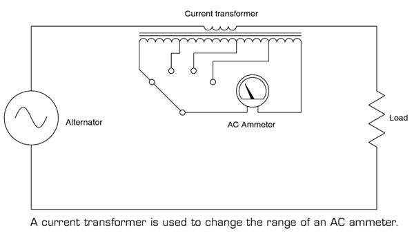
Ques.142. The breaking torque of induction type single-phase energy meter is:-
- Directly proportional to the square of the flux✓
- Directly proportional to the flux
- Inversely proportional to the flux
- Inversely proportional to the square of the flux
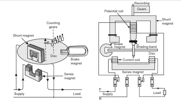
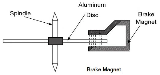
An induction-type instrument can be used as an ammeter, voltmeter, or wattmeter, the induction-type energy meters are more popular. Induction-type single-phase energy meter is used invariably to measure the energy consumed in an AC circuit in a prescribed period where supply voltage and frequency are constant. The energy meter is an integrating instrument that measures the total quantity of electrical energy supplied to the circuit in a given period. Principle The basic principle of induction-type energy meter is electromagnetic induction. When AC flows through two suitably located coils (current coil and potential coil), they produce the rotating magnetic field that is cut by the metallic disc suspended between the coils, and thus, an emf is induced in the disc that circulates eddy currents in it. By the interaction of rotating magnetic field and eddy currents, electromagnetic torque is developed that causes the disc to rotate. This is the same principle that is applied in single-phase induction motors. A single phase energy meter has four essential parts: Operating System The operating system consists of two electromagnets. The cores of these electromagnets are made of silicon steel laminations. The coils of one of these electromagnets (series magnet) are connected in series with the load and are called the current coil. The other electromagnet (shunt magnet) is wound with a coil that is connected across the supply, called the pressure coil. The pressure coil, thus, carries a current that is proportional to supply voltage. Shading bands made of copper are provided on the central limb of the shunt magnet. Shading bands, as will be described later, are used to bring the flux produced by a shunt magnet exactly in quadrature with the applied voltage. Moving System The moving system consists of a light aluminum disc mounted on a spindle. The disc is placed in the space between the series and shunt magnets. The disc is so positioned that it intersects the flux produced by both the magnets. The deflecting torque on the disc is produced by an interaction between these fluxes and the eddy current they induce in the disc. In energy meters, there is no control spring as such, so that there is the continuous rotation of the disc. Braking System The braking system consists of a braking device which is usually a permanent magnet positioned near the edge of the aluminum disc. The arrangement is shown in Figure. The emf induced in the aluminum disc due to relative motion between the rotating disc and the fixed permanent magnet (brake magnet) induces an eddy current in the disc. When disc rotates in the air gap, eddy currents are induced in the disc which opposes the cause producing them i.e. relative motion of disc with respect to the magnet. This eddy current, while interacting with the brake magnet flux, produces a retarding or braking torque. This braking torque is proportional to the speed of the rotating disc. When the braking torque becomes equal to the operating torque, the disc rotates at a steady speed. The braking torque is proportional to the flux of the braking magnet and the eddy current induced in the moving system due to its rotation in the field of the braking magnet. TB ∝ φi where φ is the flux of the braking magnet and ‘i’ the induced current. Now i = e/R where e is the induced e.m.f. and R the resistance of the eddy current path. Also, e ∝ φn where n is the speed of the moving part of the instrument. ∴ TB ∝ φ × φn/R TB ∝ φ2n/R The position of the permanent magnet with respect to the rotating disc is adjustable. Therefore, braking torque can be adjusted by shifting the permanent magnet to different radial positions with respect to the disc. By changing the distance between braking magnet and magnetic shunt, the braking torque can be adjusted. The braking torque increases when the distance between them is increased because of moving the magnetic shunt away from the magnet, it will bypass a less amount of flux and vice versa. Hence the Braking torque provided by a permanent magnet is proportional to Registering System The function of a registering or counting system is to continuously record a numerical value that is proportional to the number of revolutions made by the rotating system.Induction-type Single-phase Energy Meter
Ques.143. The application of special purpose material handling equipment is:-
- Both “Process Layout” and “line Layout”✓
- Process layout
- Line layout
- None of these
Material handling is an integral part of any manufacturing activity. A material handling system is used for handling, controlling and storage of materials. Here, the material has a very broad meaning, covering all kinds of raw materials, work-in-process, subassemblies, and finished assemblies. The primary objective of using a material handling system is to ensure that the material in the right amount is safely delivered to the desired destination at the right time and at minimum cost. Layout Type The activities involved in production or service operations may be grouped and arranged in a variety of ways. Several popular types of layout are product layout, process layout, and fixed-position layout or a combination of them. In the product layout, the product and its flow dictate the design. In the process layout, the basic organization of technology is around processes In the fixed-position layout, the construction of a large product is accomplished in one place. PRODUCT LAYOUT or LINE LAYOUT Product layout, also called mass production layout, line layout, and straight-line layout is employed when the product is produced through a continuous process. Here the raw material enters the production line, and operations are performed on it in sequence until it goes out as a finished product. The product moves continuously, perhaps down a conveyor line past successive workstations where men and machines perform the necessary operations in sequence. Automobile and home appliance lines are examples of this type of layout. When the conditions for product layout are met, we have a low-cost, highly specialized, very productive system. The requirements follow: The main advantage of product layout is its low production cost per unit Production control is relatively simple because product designs are stable and routes through the system are standardized. The disadvantages of product layout are that the investment in single-purpose equipment is high, and the system is, therefore, open to obsolescence if product designs change. Also, if a machine in the sequence breaks down or men are absent, not only is the process immediately affected delayed but perhaps the entire line is delayed. Thus, seemingly minor stoppages or material shortages could be very costly. Also, the highly repetitive nature of the work has resulted in low job satisfaction and morale in man’s instances. Product layout is most commonly used with assembly operation Fabrication lines are less common because of the difficulty in attaining ha ance between operations. A common combination is for fabrication operations to be organized on a process basis and assembly on a product fixed position basis. PROCESS LAYOUT In process layout, often called Functional and job lot layout, all machines or processes of the same generic type are grouped together in what is commonly called machine centers or departments. The departments are technologically specialized in such processes as turning, grinding, heat treating, painting, assembly, castings, accounts receivable, and typing. This layout is suitable for batch or intermittent production. Workshops producing small quantities of products or factories producing batches of made-to-order products are examples of this type of plant layout. GROUP LAYOUT Group layout is a hybrid approach combining the features of product layout m a process layout context. It is used in the more structured job shop
Ques.144. The value of the current-controlled voltage source, given β = 0.8 and Ia = 9.5mA, is
- 7.6 mV✓
- 0.0051 mV
- 0.0011 mV
- 8 mV
Current Dependent Voltage Source: It produces a voltage as a function of current elsewhere in the given circuit. This is called CDVS and it is given as va= βia = 0.8 × 9.5 va= 7.6 mV
Ques.145. The draught produced by the chimney of given height at given outside temperature
- May increase or Decrease
- Increase if the chimney gas temperature increases✓
- Decreases, if the chimney gas temperature decreases
- Remain same irrespective of chimney gas temperature
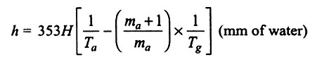
The small pressure difference which causes a flow of gas to take place is termed as a draught. The function of the draught, in the case of a boiler, is to force air to the fire and to carry away the gaseous products of combustion. In a boiler furnace, proper combustion takes place only when a sufficient quantity of air is supplied to the burning fuel. Natural Draught (chimney) Natural draught is obtained by the use of a chimney. The chimney in a boiler installation performs one or more of the following functions: (i) It produces the draught whereby the air and gas are forced through the fuel bed, furnace, boiler passes, and settings; (ii) It carries the products of combustion to such a height before discharging them that they will not be objectionable or injurious to surroundings. A chimney is a vertical tubular structure built either of masonry, concrete or steel. The draught produced by the chimney is due to the density difference between the column of hot gases inside the chimney and the cold air outside. The draught produced by the chimney is given as Where ma = Mass of air supplied ma + 1 = Mass of flue gases, pa = atmospheric pressure Ta = Temperature of atmospheric air, Tg = Average temperature of flue gases H = Height of chimney, h = Draught required in mm of water The draught of the chimney is related to the temperature difference between the flue gas and outside air as well as the height of the chimney. The higher temperature difference creates a higher draught of air-flow inside the furnace also draught is directly proportional to chimney height. In order to ensure proper draught of the chimney, its diameter and height must be calculated according to volume, average temperature, and velocity of the flue gas. 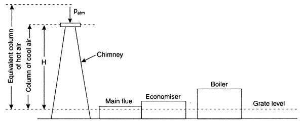
Ques.146. The chemical effect of current is used in
- D.C voltmeter
- D.C ammeter
- D.C ammeter hour meter✓
- A.C ammeter
An electrical measuring instrument depends on its operation on one of the many effects produced by current or voltage. When current flows through a wire, it produces a magnetic field as well a heating effect. When it flows through a battery, it produces a chemical effect in the electrolyte solution. In a similar way, it produces an electrostatic field and can also induce emf in a nearby circuit due to electromagnetic induction. In a secondary instrument, one of the above effects is used to produce the deflecting torque. For example,
Ques.147. The open circuit voltage of any storage cell depends on which among the following?
(i) Chemical constituents
(ii) Strength of its electrolyte
(iii) Temperature
- (i), (ii) and (iii)✓
- (ii) and (iii)
- (i) and (ii)
- Only (i)
The capacity of a storage battery is the product of the current drawn from a battery, multiplied by the number of hours this current flows. The factors upon which the capacity of storage batteries depend may be grouped in two main classifications: Design and Construction can be divided into Area of Plate Surface. The chemical and electrical activity of a battery is much higher at the surface of the plates since the acid and active material are in intimate contact here. Quantity and Strength of Electrolyte. The voltage of the battery is also dependent on the concentration of the electrolyte. The strength of the electrolyte is set high enough to provide enough sulfuric acid to satisfy the voltage and capacity limit of the battery and low enough to provide good ionic conductivity. Temperature. Chemical reactions take place much more readily at high temperatures than at low. Operating a storage battery in cold weather is equivalent to using a battery of lower capacity. For example, a fully charged battery at 26°C may be capable of starting an engine twenty times. At [17.8° C|. the same battery may start the engine only three times. Low temperatures greatly increase the time necessary for the charging & battery. A battery that could be recharged in 1 h at 26°C may require approximately 5 h of charging when the temperature is 17.8° C. These effects on a battery’s capacity are caused by the slow chemical reactions created by the cold temperatures. Chemical constituent:- Battery such as Zinc-carbon batteries, Alkaline batteries, Lithium-ion batteries (rechargeable) are used for different purposes, their life and battery capacity are also different from each other.
Ques.148. At what angle difference is the main winding and starts winding separated in a split-phase capacitor start induction motor?
- 30° mechanical
- 90° electrical✓
- 45° electrical
- 45° mechanical
Capacitor-Start Motors The capacitor start motor is identical to the split-phase motor in both construction and operation, except that a capacitor is installed in series with the starting winding, as shown in Fig. It has a single cage rotor, and its stator has two windings known as main winding and starting winding. Both the windings are displaced 90 degrees in space. Also, the starting winding of the capacitor start motor is usually wound with a larger wire than that used for the starting winding of the split-phase motor. The use of a capacitor in series with the starting winding causes the current in this winding to lead the voltage, whereas the current in the running winding lags the voltage by virtue of the high inductance of that winding. With this arrangement. the phase displacement between the two windings can be made to approach 90 electrical degrees so that the two-phase starting is achieved. For this reason, the starting torque of the capacitor start motor is very high, which makes it an ideal drive for the small compressor that must be started under full load. So if the low value of the capacitor is used in the motor the phase angle between the starting and running winding will be reduced and the motor can’t generate enough torque to rotate the motor.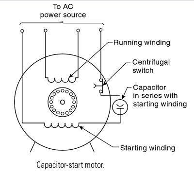
Ques.149. Calculate the minimum sampling rate to avoid aliasing when a continuous-time signal is given by:- y(t) = 5cos400πt
- 100 Hz
- 250 Hz
- 400 Hz✓
- 20 Hz
The Nyquist rate is the minimum sampling rate required to avoid aliasing. Aliasing can be defined as the phenomenon of a higher frequency in the spectrum of an original signal [say of x(t)] seemingly taking on the identity of a looter frequency in the spectrum of the sampled signal. The minimum sampling rate is given as fs = 2fm Where m is the maximum frequency where the signal can have non-zero energy. The Cosine-phase equation for a single frequency signal with frequency f and constant amplitude ymax is: y(t) = (ymax) × cos(2πft) Now comparing the given equation with the standard equation y(t) = 5cos400πt = 5cos[2π(200)t] The frequency of an analog signal is fm = 200 Hz. Therefore, the minimum sampling rate required to avoid the aliasing is fs = 2fn = 2 x 200 = 400 Hz.
Ques.150. Calculate the Nyquist rate for sampling when a continuous-time signal is given by:- x(t) = 5cos 100nt + 10 cos 200nt − 15cos 300nt
- 100 Hz
- 150 Hz
- 300 Hz✓
- 600 Hz
The highest frequency is 150Hz. Therefore fmax = 150Hz
f1 = 100π/2π = 50Hz
f2 = 200π/2π = 100Hz
f3= 300π/2π = 150Hz
Nyquist rate = 2 fmax
= 2 * 150
= 300Hz.
For UPPCL JE 2016 Electrical paper with complete solution Click Here
For UPPCL JE 2016(Evening Shift) Electrical paper with complete solution Click Here
For UPPCL JE 2018(SET – 1) Electrical paper with complete solution Click Here

