
Ques.31. Which instrument has the multiple shunt or series resistance inside the meter?
- Moving coil galvanometer
- Multimeter
- Multirange Meter✓
- Wattmeter
The multirange meters are designed to operate on more than one range. This is done by connecting the meter movement to different series shunts. Shunts are small resistances connected in parallel to increase the range of an ammeter. For multi-range ammeters, the moving coil remains the same; separate shunts are used to increase the range of measurement of a single instrument. Multipliers are high resistances connected in series with the moving coil to extend the range of measurement of PMMC type voltmeters. When a multirange meter is used, care must be taken that the shunt is never disconnected from the meter. Disconnection would cause the meter movement to be inserted in series with the circuit and full-circuit current would flow through the meter. 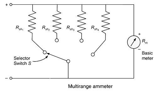
Ques.32. By which of the following elements transients will not occur?
- L
- R✓
- C
- All of these
Transient is any sudden change in the system caused by generator shifting, faults, outages, addition or removal of a heavy load, or any switching operation in the system. Transients are non-steady-state time variations of voltages and currents which occur as a result of switching circuit elements and (or) changing interconnections of electric circuits. The transients occur because of the presence of energy storage elements (i.e., inductors and capacitors). As we know that the potential difference across a capacitor cannot change instantaneously and the current through an inductor cannot change suddenly. If therefore, when a circuit containing capacitance or/and inductance is operating in the steady-state and conditions change for some reason, requiring the current and voltage values to change, there will be a finite period of time during which these changes take place. This period is called a period of transient operation. Two obvious examples of transient operation are (1) when a circuit containing capacitance or inductance is initially switched on (2) when such a circuit, having been operating in the steady-state for some time, is suddenly switched off. These transient conditions are associated with the changes in the energy stored in the capacitor or the inductor, and circuits containing either of these elements are called single energy circuits. Circuits containing both of these elements are called double energy circuits. Because there is no energy stored in purely resistive circuits, currents and voltages in such circuits are able to change without periods of transient operation (i.e. instantaneously).
Ques.33. Calculate the frequency in Hz of a 10-pole Ac generator that rotates at 1800 RPM.
- 120
- 100
- 150✓
- 180
The speed of the AC generator is given as N = 120f/P Where N = Number of revolutions per minute = 1800 RPM f = frequency P = Number of poles = 10 1800 = 120f/10 f = 150 Hz
Ques.34. Calculate the temperature coefficient in %/°C of an 8.6 V nominal zener diode at 30°C if the nominal voltage is 9.4 V at 100°C
- 0.1251
- 0.1142
- 0.1238
- 0.1321✓
The temperature coefficient of the zener diode is given as TC = (ΔV ⁄ V1) ⁄ (T2 − T1) T2 is the new temperature level T1 is room temperature in an enclosed cabinet V1 is the nominal Zener potential ΔV is the change in voltage V1 = 8.6 V. Then temperature coefficient is = [{(V2 − V1)/V1}/(T2 −T1)] × 100. = [(9.4 − 8.6/8.6)/(100 − 30)] × 100. = 0.1328 V.
T1 = 30°C.
V2 = 9.4 V.
T2 = 100°C.
Ques.35. Of what material, Swamping resistance is made up?
- Alloy of nickel and cobalt
- Alloy of manganin and aluminum
- Alloy of manganin and copper✓
- None of these
The basic sources of error in instruments are friction, temperature, and the aging of various parts. Error due to temperature: In moving iron instruments, the change in temperature affects mainly the temperature coefficient of spring. With the change in temperature, the stiffness of the spring varies which causes errors. However, for voltmeters, both the temperature coefficient of spring and the temperature coefficient of resistance of the voltmeter circuit may balance each other. Followings are the reasons for temperature error: (a) The temperatures of the ammeter coil and the shunt are not same (b) The ammeter coil and the shunt are not made of materials with the same temperature coefficient. Because of the above facts the multiplying power of the shunt changes with the temperature. This error may be eliminated by making the shunt and the ammeter coil of the same material and by maintaining the same temperature for the coil and the shunt. But both conditions are difficult to be fulfilled. A copper shunt is, likely to be bulky. Alternatively, a swamping resistance is used in series with the ammeter. The swamp resistor is made of Manganin combined with copper in the ratio of 20:1 to 30:1 and has a resistance three to four times that of the coil, which is hardly affected by temperature variations. The total resistance of the moving coil and swamping resistor increases slightly with a rise in temperature, but only just enough to overcome the effect of springs and magnets so that the overall temperature effect is zero.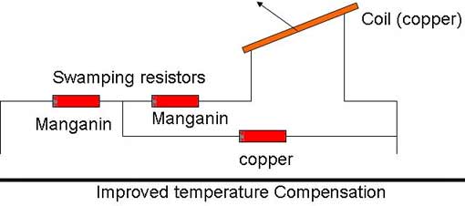
Ques 36. The output impedance of an emitter follower is
- Very high
- High
- Low✓
- Almost zero
Common-Collector Configuration In a common-collector configuration, the collector terminal of a transistor is connected as a common terminal between input and output as shown in fig. The base and collector terminals are used to apply the input signal whereas the output signal is obtained. The CC configuration is also commonly known as the emitter follower or the voltage follower. This is because the output signal across the emitter is almost the replica of the input signal with little loss. In other words, the output voltage follows the input voltage and hence the voltage gain will be a maximum of one. The common-collector configuration is used primarily for impedance-matching purposes since it has a high input impedance and low output impedance, opposite to that of the common-base and common-emitter configuration. A common-collector configuration offers the following characteristics: [ninja_tables id=”27501″]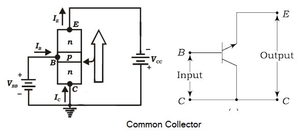
Ques.37. Alternating current is measured by:-
- Induction ammeter✓
- Electrostatic ammeter
- Moving Iron repulsion Type voltmeter
- Permanent Magnet ammeter
Induction Type Meter Induction-type instruments are used only for A.C measurement and can be used either as an ammeter, voltmeter or wattmeter. However, the induction principle finds its widest application as a watt-hour or energy meter. In such instruments, the deflecting torque is produced due to the reaction between the flux of an ac magnet and the eddy currents induced by another flux. Principle of Operation. a thin aluminum or copper disc D free to rotate about an axis passing through its center as shown in Figure. Two electromagnets P1 and P2 produce alternating fluxes φ1 and φ2 respectively which cuts this disc. Since the operation of induction type instruments depend on the production of torque due to the interaction between a flux φ1 (whose magnitude depends on the current or voltage to bc measured) and eddy current induced in a metal disc or drum by another flux φ2 (whose magnitude also depends on the current or voltage to be measured). Since the magnitude of eddy current also depends on the flux producing them, the instantaneous value of the torque is proportional to the square of current or voltage under measurement and the value of mean torque is proportional to the mean square value of this current or voltage. The induction type meter can be either of Ferrari’s type or shaded pole type. When used as an ammeter current to be measured or a part of it is passed through the operating coil of the instrument. However, when used as a voltmeter current proportional to the voltage to be measured is passed through the operating coil. Td ∝ I2 Td ∝ V2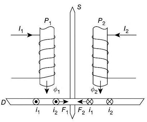
Ques.38. Which among the following is the important component of the value of critical density in a superconductor?
- Magnetic field strength and temperature✓
- Current gain
- Resonance
- Power
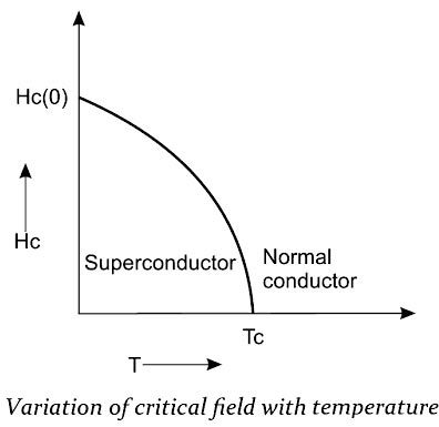
Superconductivity is a phenomenon in which certain metals, alloys, and ceramics conduct electricity without resistance when it is cooled below a certain temperature called the critical temperature. A superconductor is a material that loses all its resistance (offers zero resistance) to the flow of electric current when it is cooled below a certain temperature called the critical temperature or transition temperature TC. Examples: Mercury (Hg), Zinc (Zn), Vanadium (V), Tin (Sn) and Niobium (Nb). Properties of Superconductors A few important properties of superconductors are explained in brief in this section. (i) Critical temperature TC (Transition Temperature) The electrical resistance of the superconducting materials becomes zero below the transition temperature (Tc). This property is called the defining property of superconductors. The figure shows the variation of electrical resistance with respect to the temperature for the normal conductor and a superconductor. From the figure, it is noted that the resistance falls to zero at the transition temperature. Note:- Good electrical conductors such as silver (Ag), Gold (Au) and copper (Cu) are not good superconductors because the resistivity of these conductors at low temperatures is limited to the low resistivity. Similarly, good superconducting materials like Zn and Pb are not good electrical conductors. (ii) Magnetic field effect If a sufficiently strong magnetic field is applied to a superconductor at any temperature below its critical temperature TC, the superconductor is found to undergo a transition from the superconducting state to the normal state. This minimum magnetic field required to destroy the superconducting state is called the critical magnetic field HC. (iii) Electrical resistance:- The electrical resistance of a superconducting material is very low and is of the order of 10–7 Ωm. (iv) Effect of impurities:- When impurities are added to superconducting elements, the superconducting property is not lost, but the TC value is lowered. (v)Critical current density JC and critical current IC The critical current density is another important characteristic feature of the superconducting state. When the current density through a superconducting sample exceeds a critical value JC. the superconducting state is found to disappear in the sample. This happens because, the current through the superconductor itself generates a magnetic field, and at a sufficiently high current density the magnetic field will start exceeding the critical magnetic field HC thereby making the superconducting state to disappear in the material. Hence, the critical current density can be defined as the maximum current that can be permitted in a superconducting material without destroying its superconductivity state. The critical current density is a function of temperature, i.e., the colder the temperature for a superconductor the more is the current it can carry. (v) Effect of pressure and stress:- Certain materials are found to exhibit the superconductivity phenomena on increasing the pressure over them. For example, cesium is found to exhibit superconductivity phenomena at TC = 1.5 K on applying a pressure of 110 Kbar. In superconductors, the increase in stress results in an increase of the TC value. (vi) Isotope effects:- The critical or transition temperature TC value of a superconductor is found to vary with its isotopic mass. This variation in TC with its isotopic mass is called the isotopic effect. The transition temperature is inversely proportional to the square root of the isotopic mass of a single superconductor.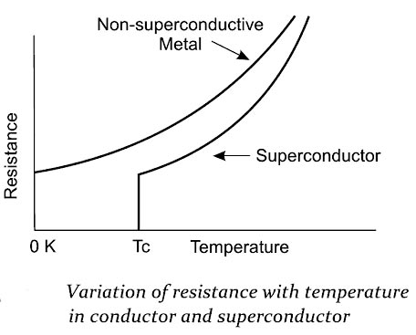
Ques.39. Which among the following indicates early effect in BJT?
- Zener breakdown
- Avalanche breakdown
- Base narrowing✓
- Thermal breakdown
In an ideal transistor, it is assumed that the base width remains constant. But in real bipolar junction transistor, the base-collector region is reverse biased, therefore, as the reverse bias across the base-collector junction is increased, the base-collector junction depletion-layer width increases. in the case of PN junction, the junction potential is directly proportional to the square of the width of the depletion layer. In equation form, we express this as Vj ∝ W2 From this, we conclude that the junction width can be varied by varying the applied voltage. In a bipolar junction transistor, we have its emitter-base junction forward biased. This voltage creates a narrow depletion layer between the base and the emitter. Similarly, its collector-base junction is reverse biased, which creates a wider depletion layer between the base and the collector. The depletion region reduces the effective width of the base and hence reduces the chances of recombination in the base. This, in turn, increases the collector current with applied voltage. This effect is called the Early effect. It is also known as the base-width modulation or base-narrowing effect as the base width gets modulated or narrowed with the applied voltage.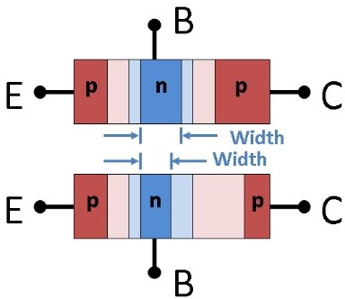
Ques.40. Select the advantages of three-phase induction motor over single-phase induction motor.
(i) self-starting motor
(ii) Better power factor
(iii) High efficiency
- (i), (ii) and (iii)✓
- (ii) and (iii)
- (i) and (ii)
- (i) and (iii)
Comparison Between three-phase induction motor and Single phase Induction motor

