
Ques.81. Voltage drop in an alternator can be determined by which of the following factor?
- Power factor × load current
- Power factor × (load current)2
- Load current✓
- Voltage drop of the load
Load current:- Load current is the current that the appliance is drawing at that instant. It should always be lower than the rated current of that item. Rated current is the maximum current an appliance should ever draw. The terminal voltage of a dc generator varies with a variation in the load current. In the alternator also, the terminal voltage changes with the load current due to the following factors. 1. The voltage drop in the resistance of the armature, 2. Voltage drop in the leakage reactance of the armature, and 3. Voltage drop due to the armature reaction which depends on the power factor of the load. Voltage Drop Due to Armature Resistance The stator of an alternator carries armature conductors which are distributed 3-phase windings. The resistance of the armature windings is known as the armature resistance. Whenever the armature carries the load current, there will be a voltage drop in the armature resistance. If Ra is the armature resistance per phase and la is the armature current per phase, then the voltage drop across Ra will be la Ra volts, which will be in-phase with the armature current la. Additional energy loss such as Hysteresis loss, Eddy current Loss, and loss due to unequal distribution of currents are part of armature resistance losses. Armature Leakage Reactance Armature Reaction When the load is connected to the alternator, the armature winding of the alternator carries a current. Every current carrying conductor produces its own flux so armature of the alternator also produces its own flux when carrying a current. So there are two fluxes present in the air gap, one due to armature current while second is produced by the field winding called main flux. The flux produced by the armature is called armature flux So the effect of the armature flux on the main flux affecting its value and the distribution called armature reaction. ALTERNATOR REGULATION Regardless of the type of generator or alternator used in a system, the terminal output voltage of the machine varies with any change in the load current. The impedance of the windings and the power factor of the load circuit both influence the regulation of an alternator. An increase in load current in a pure resistive load circuit causes a decrease in output voltage. A voltage drop of approximately 10 percent is common when going from a condition of no load to full load in a typical alternator without voltage regulation controls. For an inductive load, an increase in load current will cause a greater voltage drop than is obtained with a pure resistive load. A load with a low value of lagging power factor produces a large drop in output voltage. A capacitive load circuit produces the opposite effect. In other words, thc output voltage rises above the no-load value with an increase in load current and is high at a low value of leading power factor.
Ques.82. The self-induced voltage of a current-carrying coil which is wound on the iron core having 1A currents is independent of _____
- Number of turns of coil
- Variation in current
- Variation in voltage to the coil✓
- The resistance of the magnetic path
The self-inductance of the coil can also be written as L = μN2A/I where N is the number of turns of the solenoid A is the area of each turn of the coil l is the length of the solenoid and μ is the permeability constant hence the self-inductance does not vary with change in the voltage.
Ques.83. Pugga valley in Ladakh is suitable for which of the following power generation?
- Wind
- Solar
- Geothermal✓
- All of these
Ques84. Due to overdamping, the instrument will become:-
- Both lethargic and slow✓
- Fast
- Slow
- Lethargic
Damping Torque A damping force is one which acts on the moving, system of the instrument only when it is moving and always opposes its motion. Such stabilizing or damping, force is necessary to bring the pointer to rest quickly otherwise due to inertia of the moving system, the pointe will oscillate about its final deflected position for quite sometime before coming to rest in the steady position The degree of damping should be adjusted to a value which is sufficient to enable the pointer to rise quickly to its deflected position without overshooting. In that case, the instrument is said to be dead-beat. If the instrument is underdamped, the pointer will oscillate about the final position and take some time to coming to rest. An increase of damping above this limit i.e. overdamping will make the instruments slow and lethargic. In Fig. 10.4 is shown the effect of damping on the variation of position with the time of the moving system of an instrument. The damping force can be produced by
Ques.85. Hall effect may be used for which of the following?
- Detecting aircraft communication signals
- Determine the carrier concentration
- Determine whether the semiconductor is P or N type✓
- Calculating the mobility
A Hall effect sensor is a transducer that produces its output voltage in response to changes in magnetic fields. Applications of Hall effect sensor are
Ques.86. Hysteresis loss in a transformer is proportional to which of the following quantity?
- Bmax
- Bmax1.6✓
- Bmax0.6
- Bmax1.06
Hysteresis loss: A transformer core is made up of ferromagnetic material and these materials are very sensitive to magnetization. These materials behave as magnates when the external magnetic field is applied. These materials having the number of domains in their structure and the domains are nothing but small permanent magnets whose axes are randomly oriented inside the material so net magnetization is zero. But when an external magnetic field is applied, the axes of domains(small magnets) get aligned to the axis of externally applied magnetic field and when this external magnetic field is removed, maximum domains attain their original position but some of them do not attain their position means material do not demagnetize completely and this is the reason for hysteresis loss. In the transformer, we give AC supply so after each half cycle reversal of external magnetic field, so there is a reversal of domain, Hence extra work has to be done to completely reverse it and this extra work needs electrical energy which results in hysteresis loss. Hysteresis Losses in a transformer is given by Hysteresis Loss = Kh × BM1.67 × f × v watts where
Kh = Hysteresis constant depends upon the material
Bm = Maximum flux density
f = frequency
v = Volume of the core
Ques.87. A power supply should possess an ideal voltage regulation which is equal to ______ and practical voltage regulation measuring ______
- Small Value, Zero
- Zero, small value✓
- Zero, Zero
- Large value, Zero
A power supply should possess an ideal voltage regulation that is equal to Zero and practical voltage regulation measuring a small value. Voltage regulation. The ratio of the change in dc voltage from no load to full load with respect to the full load voltage of a power supply is known as its voltage regulation. Voltage Regulation = (VNL − VFL) ⁄ VFL An ideal power supply is one for which VNL = VFL, it requires 0% regulation. In actual practice, however, no-load and full load respectively refer to the minimum and maximum limits of load current within which the regulation is required. The smaller the percentage regulation, the better is the supply. In a well-regulated power supply percentage, regulation should not be more than 1%.
Ques.88. A D.C series motor is that which
- Has a poor torque
- Has its field winding consisting of thick wire and less turns✓
- Has almost constant speed
- Can be started easily without load
In a dc series, motor and generator respectively as the field winding is connected in series with the armature, If= Ia = IL. In the case of a dc series machine, therefore, the field winding is made up of thick winding wires such that the armature current can flow through wires of the field winding without overheating. Also since the series winding carries the whole of load current, it is designed to have very low resistance (about 0.5Ω). For this reason, series field winding has a few turns of thick wire.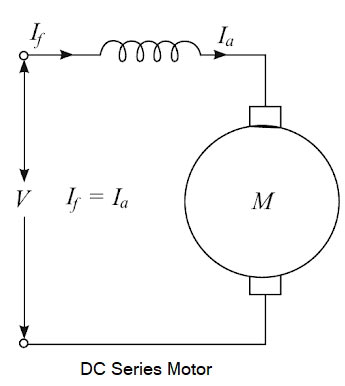
Ques.89. Which coupling is very expensive?
- Transformer✓
- Stamp
- External
- Control
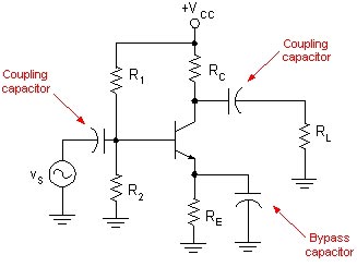
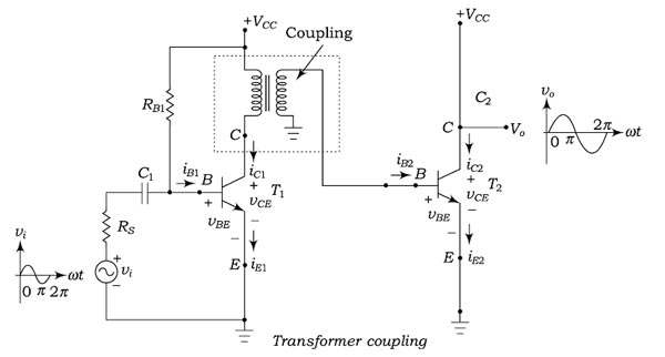
Function of the coupling capacitor In analog circuits, a coupling capacitor is used to connect two circuits such that only the AC signal from the first circuit can pass through to the next while DC is blocked. This technique helps to isolate the DC bias settings of the two coupled circuits. Capacitive coupling is also known as AC coupling and the capacitor used for the purpose is also known as a DC-blocking capacitor. Transformer coupling The Transformer coupling is shown in Fig and is mostly employed for impedance matching. In general. the last stage of the multistage amplifier is the power stage. This stage delivers the maximum power to the load e.g. a loudspeaker. For maximum power transfer, the impedance of power source must be equal to that of the load. In this scheme, the primary winding of the transformer is used as a collector load and the secondary winding of transformer transmits the ac output voltage signal directly to the base of the next-stage amplifier. Hence there is no requirement of coupling capacitors. Moreover, the secondary winding also provides a base return path, and there is no need for base resistance. Amplifiers using this coupling are called transformer-coupled. Transformer coupling provides perfect d.c. blocking and good impedance matching. However, for wideband, audio or low-frequency operation, the value of inductance required makes the size and weight of the transformer large, and therefore, impractical. In addition, such transformers are considerably more expensive than components required for the other forms of inter-stage coupling mentioned. For high-frequency work, though, the transformer is a highly efficient and practical method of coupling. The use of transformers with tuned primary and secondary windings allows a narrow band of frequencies to be coupled, providing a means of rejecting signals at unwanted frequencies. The use of transformers for inter-stage coupling also allows the circuit designer to match the output impedance of one stage to the input of the next. This method provides a high degree of impedance matching and, in turn? a high level of power transfer occurs.
In most of the practical case, you will not see the single amplifier. Rather than you will see a series of the cascaded amplifier. The term cascaded means connected in series. Coupling capacitors are commonly used to connect one amplifier stage to the another.
Ques.90. Which type of following product is used to make insulating in spark plugs?
- Nickel alloy
- Porcelain✓
- Glass fiber
- None of these
A spark plug is a device for delivering electric current from an ignition system to the combustion chamber of a spark-ignition engine to ignite the compressed fuel/air mixture by an electric spark while containing combustion pressure within the engine. A spark plug entails the following requirements:- Porcelain is commonly used as insulating material in spark plugs, as it is cheap and easy to manufacture. Mica can also be used as an insulating material for spark plugs. Mica, however, cannot withstand high temperatures successfully.

