Ques.111. Which of the following groups are examples of insulators?
- Plastic, silver, aluminum, wood
- Glass, plastic, wood, porcelain✓
- Glass, aluminum, wood, rubber
- Air, plastic, wood, copper
When an electric field is applied to a conductor, there occurs a large scale physical movement of free electrons because these are available in large numbers in Conductor. The resistivity of the conductor is 10−8 to 10−6. On the other hand, if an electric field is applied to an insulator, there is hardly any movement of free electrons because these are just not available in an insulator. Plastics, wood, and rubber are examples of good insulators. Pure water is also an insulator. Tap water, however, contains salts that form ions which can move through the liquid, making it a good conductor. The insulator is also called the dielectric. There are practically no free electrons in the dielectric. The electrons in dielectric normally remain bounds to their respective molecules. The resistivity of the insulator is 107 to 1023.
Ques.112. Which of the following part or auxiliary is not used in the diesel power station?
- Lubricating system
- Fuel supply system
- Steam generating system✓
- Intake air system
Diesel engine power plants are more efficient than the other types of engine plant for the same capacity. The diesel engine plants are more suitable for low- and medium-power outputs. These plants are commonly employed where fuel prices are low and water availability is limited. The capacity of the diesel power plants is about 5 MW, such plants are used as standby plants to hydro- and diesel power plants for small output.
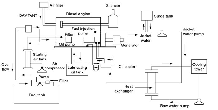
(i) Air intake and exhaust system: This system consists of pipes arrangement for admitting fresh atmospheric air into the diesel engine, and also to pump out the exhaust gases to the atmosphere. Filters are needed at the air inlet to remove dust particles etc. from the incoming air. At the outlet of the system, the silencer is provided to reduce the noise when the exhaust gases are coming out from the engine.
In order to reduce the specific fuel consumption and to increase the engine capacity, the intake system must have to maintain minimum pressure loss.
(ii) Fuel supply system: This system consists of the fuel tank to store fuel, and fuel pumps and fillers lo transfer and inject fuel into the diesel engine. Fuel oil is supplied by trucks, rail, cars, etc. at the plant site.
(iii) Cooling system: This system circulates a sufficient amount of water around the engine in order to maintain the desired temperature. The hot water re-cooled in the cooling ponds again recirculated into the system.
(iv) Lubricating system: This system is necessary to reduce ware on the rubbing parts and friction. It consists of the lubricating oil tank, pumps, filters, etc.
The diesel engine is nothing but internal combustion engine, in which fuel is ignited by injecting into system thereby compression. So that these engines are also called as compression ignition engines. This engine will convert heat energy into mechanical work. In the combustion chamber, fuel burns rapidly and gases attain the very high temperature and produce extremely hot compressed gases. These gases expand and push back the piston of the engine. This is nothing but the power stroke in which mechanical work is done. This work is helpful to rotate the crankshaft on which generator is mounted, which converts mechanical power into electric power.
(v) Starting system: Starting system is essential for the initial starting of the engine. It consists of the compressor, battery, and electric motor (or) self-starter.
Note:- Steam generator or boiler is usually found in the thermal power plant.
Ques.113. Which of the following diodes is also known as a hot carrier diode?
- Varactor diode
- PN diode
- Schottky diode✓
- LED
The Schottky diode (named after the German physicist Walter H. Schottky), is a semiconductor diode formed by the junction of a semiconductor with a metal. They are also known as hot carrier diodes. This name comes out as follow. Forward bias increases the energy of the electrons on the N side to a higher level than that of the electrons on the metal side of the junction. This increase in energy inspired the name hot carrier for the n-side electrons. As soon as these high-energy electrons cross the junction, they fall into the metal, which has a lower-energy conduction band.
A Schottky diode is formed by joining a doped semiconductor region (usually n-type) with a metal such as gold, silver or platinum. Rather than a PN junction, there is a metal-to-semiconductor junction. The forward voltage drop is typically around 0.3 V.
The Schottky diode operates only with majority carriers there are no minority Carriers and thus no reverse Leakage current as in other types of diodes. The metal region is heavily occupied with conduction band electrons, and the n-type semiconductor region is lightly doped. When forward-biased, the higher energy electrons in the n region are injected into the metal region where they give up their excess energy very rapidly. Since there are no minority carriers, as in a conventional rectifier diode, there is a very rapid response to a change in bias. The Schottky is a fast-switching diode and most of its applications make use of this property. It can be used in high-frequency applications and in many digital circuits to decrease switching times.
Ques.114. Which of the following scales offers the widest range for measurement through an instrument?
- Logarithmic scale✓
- Exponential scale
- Linear scale
- Square-law scale
Various Scales— 1. Linear Scales:- A linear scale like a foot rule, is the simplest to read. Though termed as linear it may form a part of the arc, however, the graduations will be uniformly disturbed. The moving coil electrodynamic wattmeters generally have the linear scale. Moving iron instruments also have nearly linear scales. 2. Square low scale:- Some instruments like thermal instruments, electrodynamic voltmeters, and ammeters follow the square law scale. 3. Logarithmic scale:- The logarithm and its use is nothing more than a mathematical tool which simplifies dealing with very large and very small numbers. For example, the logarithm of the number 1,000,000 is six, and the logarithm of the number 0.000001 is -six (minus six). Obviously, as more zeros are added before or after the decimal point, convening these numbers to their logarithms greatly simplifies calculations which use these number. If the current to be measured extends over a wide dynamic range, for example spanning several orders of magnitude, there is a risk that the signal conditioning circuit can saturate at its upper or lower limit and no measurement will be obtained. This problem can arise in the measurement of photocurrents in the atmosphere which span a large range of values during the daytime, and in atmospheric electricity measurements where currents generated in elevated points vary between HA in disturbed weather to pA in fair weather. An alternative approach for current measurement is therefore needed if, in preserving the capability to measure large currents, good resolution is still required at the low current end of the range. A wide operating range can be achieved with a logarithmic current amplifier, which generates an output voltage proportional to the logarithm of the input current. This can be implemented with an opamp by using a device having an exponential voltage-current response in place of the feedback resistor of the trans-resistance configuration, such as a diode. Similarly, we use logarithmic scales for things that come in an extremely wide variety of sizes. Earthquakes are just one example: a 9.0 earthquake releases a trillion times as much energy as a 1.0 earthquake. If we used a linear scale, we would have to use giant numbers to describe earthquakes; for example, a 6.0 magnitude earthquake would be a 1,000,000,000 size earthquake, and a 9.0 magnitude earthquake would be described as a 1,000,000,000,000 size earthquake.
Ques.115. Which of the following is used to neutralize the Ferranti effect in the medium and long transmission lines?
- Shunt capacitor
- Series resistor
- Series capacitor
- Shunt reactor✓
A long transmission line can be considered to be composed of a high amount of capacitance and inductor distributed across the entire length of the line. Ferranti Effect occurs when current drawn by the distributed capacitance of the line is greater than the current associated with the load at the receiving end of the line which occurs during light or no load. Shunt Reactor compensation at the receiving end help to reduce the effect of capacitance thus reducing the Ferranti effect. Shunt Reactor absorbs the excess reactive power during no load or light load condition and thus helps in stabilizing the voltage of Transmission Line.
Ques.116. Which of the following semiconductor materials is used to make green LEDs?
- Indium Gallium aluminum Phosphide✓
- Gallium Arsenide Phosphide
- Gallium arsenide
- Aluminium Gallium Arsenide
LEDs are semiconductors that convert electrical energy into light energy. The colour of the emitted light depends on the semiconductor material and on its composition. LEDs are formed from various doped semiconductor materials in the form of a PN junction. When an electrical current passes through the junction in the forward direction, the electrical carriers give up energy in the form of photons at a level proportional to the forward voltage drop across the diode junction. The semiconductor material typically takes the form of a very small chip or die, which is mounted onto a lead frame and encapsulated in a clear or diffused epoxy. The shape of the epoxy and the amount of diffusing material in the epoxy control the light output angle of emission. Blue to Green LEDs: 450 to 530 nm The material for this wavelength range of products is Indium Gallium Nitrate InGaN. Most large suppliers concentrate on creating blue (450-475 nm) LEDs for making white light with phosphors, and green LEDs that fall into the 520 to 530 nm range for green traffic signal lighting. Yellow-Green to Red LEDs: 565 to 645 am Aluminum indium gallium phosphide (AllnGaP) is the semiconductor material used for this wavelength range. It is predominately used for amber traffic signals (590 nm) and red (625 nm) lighting. The lime green (or yellowish-green 565 nm) and orange (605 nm) are also available from this technology, but they are somewhat limited. The technology is rapidly advancing, for the red wavelength in particular, because of the growing commercial interest in making red-green-blue white LED lights. Other semiconductor used for making Greenlight is Aluminium Gallium Phosphide AlGaP Gallium Phosphide GaP Gallium Nitrate GaN Indium Gallium Nitrate InGaN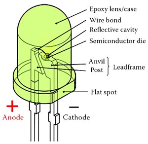
Ques.117. Which of the following are the functions of a transistor?
- Rectifier and fixed resistor
- Switching device and fixed resistor
- Tuning device and rectifier
- Variable resistor and switching device✓
The transistor is a semiconductor device made by joining together three layers of P and N-type material. Operating a transistor When you design a transistor circuit, you choose components that will put the transistor into the right operating mode (cutoff, active, or saturation), depending on what you want the transistor to do. Here’s how: Transistor as a variable Resistor:- The operation of a transistor could be explained by making an analogy to faucets. The emitter is the source (as in the water supply). The handle of the faucet is equal to the base whereas the end of the opening where water will flow from is the equal of the collector. In a transistor, the collector is the output whereas the emitter is the input This leaves the base as the controller of current between the emitter and collector. By applying a high enough voltage to the base (like exerting pressure on a faucet handle), you switch the transistor on, and current flows from the collector to the emitter (like the water flows through the pipe part of the faucet). If the voltage at the base is too low, you switch off the transistor, and no current flows from the collector to the emitter. When the transistor is switched on, you control the amount of current that flows from the collector to the emitter by controlling how much current flows into the base of the transistor. And the nice part about this fact is that small current in the base control large currents flowing from the collector to the emitter. It is correctly said that the transistor is nothing but the variable resistor. The resistance between collector and emitter depends upon the base current. Higher is the base current lower is the resistance between collector and emitter and at that time transistor is said to be in ON state. Collector current, IC = β × Ib(base current) Transistor amplifier: if you want to use the transistor as an amplifier (active model, you select supply voltages and resistors to connect to the transistor so that you forward-bias the base-emitter junction and allow just enough base current to flow—but not so much that the transistor becomes saturated. This selection process is known as biasing the transistor. Transistor switch: If you want the transistor to act like an on/off switch, you choose values of supply voltages and resistors so that the base-emitter junction is either nonconducting (the voltage across it is less than 0.7 V) or fully conducting—with nothing in between. When the base-emitter junction is nonconducting, the transistor is in cutoff mode and the switch is off. When the base-emitter junction is fully conducting, the transistor is in saturation mode and the switch is on.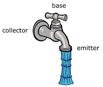
Ques.118. Which of the following is correct about the gain of a cascade amplifier?
- Total gain is a sum of individual gains✓
- Total gain is a product of voltage and current gains
- Total gain is a product of individual gains
- Total gain is a ratio of individual gains
N-STAGE CASCADED AMPLIFIER Cascading of Amplifiers is a process of connecting a set of Amplifiers in series with the output voltage of one stage applied as the input voltage to the next following stage input port through inter-stage coupling elements or direct coupling. The figure shows a cascaded Amplifier with three stages of Amplifiers having gains A1, A2 and A3. Consider an external input signal voltage Vin applied to the first amplifier stage. Then the output voltage of the first amplifier stage will be A1.Vin. Through any one type of coupling elements such as a capacitor, inductor or a transformer, the output of the first amplifier stage will be connected to the input port of the second amplifier stage. Assuming no loss of signal during transmission through the coupling element, the input signal to the input port of the second amplifier stage is A1.Vin. The output voltage of the second amplifier stage is A1.A2.Vin. This signal again forms the input signal to the third amplifier stage. Then the output signal Vout of the third amplifier stage is A1.A2.A3.Vin. Now the gain A of this three-stage cascaded Amplifier is the ratio of Vout to Vin. The total gain A of the cascaded Amplifier is the product of the gains of the individual stages, which is A1.A2.A3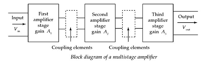
Ques.119. Which of the following electrical element exhibits non-linear voltage-current characteristics?
- Resistor
- Inductor
- Diode✓
- Capacitor
A nonlinear device is a device which does not have a linear input/output relation. In a diode, for example, the current is a non-linear function of the voltage. For a device to be linear, when one of its parameter changes, its other parameter should also change accordingly with the same magnitude. Like, if we have a 2-ohm resistor, and we apply 2 amp current across its terminals, the output voltage would be 4 V. If we double the current i.e. supply 4 amp then the output voltage would be doubled as well. So, the resistor is a linear device. However, changing the voltage or current across a diode does not result in a corresponding change in current or voltage, respectively. Typical I-V diode characteristics are shown in Figure. In the case of a common silicon diode, the forward-direction current increases exponentially at first, and then is limited by an ohmic resistance of the structure. A very small reverse current at first increases slightly with applied voltage and then starts to multiply near the breakdown voltage. The current at the breakdown is limited by ohmic resistances of the structure. The voltage or current do not change with the same magnitude as the change in current or voltage, respectively. So, we can say a diode has a variable resistance. Since a diode has a variable resistance, it is a non-linear device.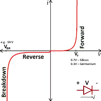
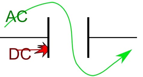
Ques.120. Which of the following statements is correct about capacitors?
- None of these
- The capacitor disconnects short circuit in direct current (DC) and alternating current (AC) circuits
- The capacitor disconnects short circuit in both direct current (DC) and alternating current (AC)
circuits - The capacitor disconnects current in the direct current (DC) circuit and short circuit in alternating current (AC) circuits✓
Just like resistors, capacitors also offer some form of resistance against the flow of current through the circuit, but with capacitors in AC circuits this AC resistance is known as Reactance. Capacitive Reactance = 1/2πfC As frequency is increasing the capacitive reactance is slowly reaching zero value. In AC circuit we suppose that the frequency value is sufficiently high to make capacitive reactance zero or the capacitor behaves equivalent to short circuit. or When the frequency of input signal is very low, or zero, it will charge in few time constants (i am assuming time constant is very low) and then stay that way, and discharge only when the signal voltage goes lower than capacitor voltage. If its zero, only charging will take place when supply is on, which is why it becomes open circuit after a few time constants. On other hands, in case of very high-frequency signals, the capacitor will charge and discharge so rapidly that it appears as if the capacitor is conducting, thereby acting like a short (though not an ideal short circuit).