
Ques.131. Gold is an example of which of the following?
- Conductor✓
- Semiconductor
- Magnet
- Insulator
When an electric field is applied to a conductor, there occurs a large scale physical movement of free electrons because these are available in large numbers in Conductor. The resistivity of the conductor is 10−8 to 10−6. Gold is a pretty good electrical conductor. It is almost as good as silver and copper. So its third in conductivity among the metals. And since it does not corrode or oxidize, it is often used for the connector and switch contacts to ensure low resistance at the point of contact. Since its very expensive, connector and switch contacts are often plated with gold at the surface to a few microinches rather than being solid.
Ques.132. What can we reduce by using thin lamination in a machine?
- Hysteresis losses
- Iron Losses
- Eddy current Losses✓
- Cooper losses
Eddy-current loss occurs whenever the core material is electrically conductive. It is the heat dissipation caused by the eddy current le flowing through the core resistance R (can be calculated by Ie2R). Since power is proportional to the square of the applied voltage in a circuit, i.e., P = V2/R while the induced voltage is proportional to fB, the eddy-current losses are proportional to f2B2, while B itself is related to the size of the loop. To reduce the eddy-current loss, a laminated core (consists of a stack of thin slices instead of a solid core) is used. The eddy-current loss is inversely proportional to the square of the number of laminations. To further reduce the eddy-current loss, an iron dust core that divides up the iron into fine particles (to prohibit the eddy-current flow) is invented, where the iron is ground into a powder, mixed with some insulating binder or matrix material and then fired to produce a core shape. Such a core can operate at several MHz, but its permeability is lower than a solid iron. In a transformer, the eddy current loss is proportional to the square of the diameter of the core. Hysteresis and eddy-current losses are collectively known as core loss.
Larger the diameter, more the eddy current loss.
Hence transformer core is laminated so that the net effective diameter of the transformer core reduces and thus eddy current loss can be minimized
Ques.133. In a combinational circuit, which is used to send more data through a single transmission?
- Encoder
- Demultiplexer
- Multiplexer✓
- Decoder
Signals, after conditioning may have to be sent to different places for display or recording and for control purposes. Signals are normally transmitted along fiber optic cable. Analog signals are converted to digital form using an A to D (Analog to Digital) converter. If there is the requirement of sending more than one signal, it is economical to use a single cable rather than using separate cables for communication. Multiplexing involves switching the analog signal in turn, in a synchronized sequential manner to the A to D converter which is connected to the transmission line. At the other end of the line digital to analog converter converts the received signal back to analog form and used. So, multiplexing allows a single channel to share more than one quantity to be transmitted through. A multiplexer accepts multiple analog inputs. It can transmit more than one signal using the same channel. Multiplexers are used when many signals are to be transmitted and the distance is large. Use of multiplexer in a data acquisition system for transmission has been shown in a block diagram form in Fig. At the receiving end (not shown in the figure) the data is converted back to analog form using a D to A converter and then connected to meters, recorders and display devices as per need through a multiplexer. So, multiplexing is a system that helps in transmitting multiple signal data through one single cable. Multiplexing can be done on time sharing basis where multiple inputs to the channel are sampled very rapidly one after the other for fixed period of time. Each set of data is sent one after the other and the process is repeated continually.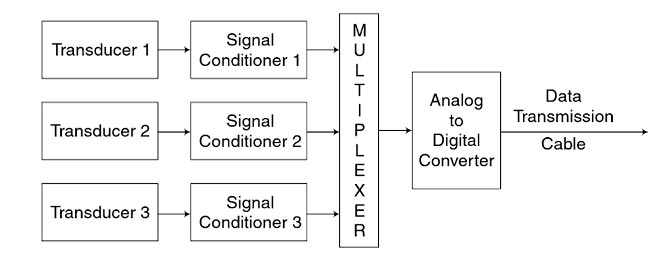
Ques.134. Heat is transferred simultaneously by condition, convection, and radiation:-
- During melting of ice
- Inside boiler furnace✓
- From refrigerator coils to freezer of a refrigerator
- Thorugh the surface of the insulated pipe carrying steam
A furnace is the primary part of the boiler where the chemical energy available in the is converted into the thermal energy by the combustion process. HEAT TRANSFER IN BOILERS An understanding of heat transfer is a fundamental requirement for a boiler operator. There are three ways that heat is transferred, conduction, radiation, and convection and all three mean occur in a boiler. The fundamentals of these heat transfer processes are individually simple, but the applications are complex because of the simultaneous occurrence of several modes of heat transfer, irregular shapes involved, dynamic conditions, and so on. That is why heat transfer is a not-so-exact science, as the variables are many and the situations dynamic Also, a very large body of data on fundamental properties of materials is required. Heat Transfer by Conduction Heat energy can be transferred from one substance to another when they are in direct contact. This type of heat transfer takes place in solid objects. Heat transfer in this method is linearly related to the temperature difference. This method of heat transfer is called as conduction. Conduction method of heat transfer is mainly seen in solid objects. It happens when any ho material comes in contact with a cold material. When heat is transferred through conduction the substance itself does not move; rather, heat is transferred internally by vibrations of atoms and molecules. Electrons can also carry heat. Metals have many free electrons which mov^t around randomly. They can transfer heat from one part of the metal to another. So, metals art generally a good conductor of heat. Some solid materials arc better conductor of heat than the others. For example, metals are good conductors of heat while a material like wood is not. When a metal is heated at one end, the other end also becomes hot while that does not happen with a piece of wood. Good conductors of electricity are often good conductors of heat. Since the atoms are closer together, solids conduct heat better than the liquids or gases This means that two solid materials in contact would transfer heat from one to the other better than a solid in contact with a Qua or a ~,~a,s with a liquid. Heat flow from flue gases to water/steam across the metal wall in a boiler, loss of furnace heat to the surrounding atmosphere through insulation, and heat loss from hot steam/water pipes through insulation are all examples of conduction. HEAT TRANSFER BY CONVECTION Molecules of a liquid and gas are not confined to a certain point. They change their position, In this case, heat energy is transported from one point to another by the movement of these molecules. This phenomenon of heat transfer is called as convection. Heat transfer in fluids is generally done through convection. Hotter part of the fluid is not as dense as the cooler part, so there is an upward buoyant force on the hotter fluid, making rise while the cooler and denser fluid sinks. The convection current is set up in the fluid. Convection may take place naturally through the creation of convection current or by applying some external force. Convection in a boiler is due to the movement of hot gases over the stock surface. Heat transfer through Radiation:- Radiation is the transfer of heat by electromagnetic waves from the surface without the need of any medium. Heat flow in a boiler furnace is almost entirely by radiation. Radiation wave is generated from the flame, hot combustion product and through the wall of the furnace.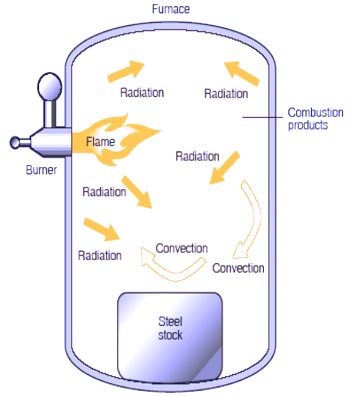
Ques.135. Which material used in commutator brushes?
- Mica
- Carbon✓
- Copper
- Cast Iron
Ques.136. Which motor is used in the centrifugal pump?
- Split phase Induction Motor✓
- Shaded pole induction motor
- Squirrel cage motor
- Capacitor start/capacitor run induction motor
A centrifugal fan is a mechanical device for moving air or other gases. The terms “blower” and “squirrel cage fan“, (because it looks like a hamster wheel), are frequently used as synonyms. Centrifugal fans are constant displacement with normal starting torque devices or constant volume devices, meaning that, at a constant fan speed, a centrifugal fan moves a relatively constant volume of air rather than a constant mass. This means that the air velocity in a system is fixed even though the mass flow rate through the fan is not. For blower applications, the most common motors are 2-pole (3600 rpm), 4 poles (1800 rpm), and 6-pole (1200 rpm). The most preferred motor for the blower is squirrel cage induction motor, synchronous motor, DC shunt Motor, Split-phase motor. Explanation:- Since in case of the centrifugal pump the most preferred motor is squirrel cage induction motor. In squirrel cage induction motor. This rotor has low starting torque per ampere of starting current. The starting current is high, and these motors exhibit good running torque. Motors containing rotors of this type generally have very good speed regulation and low percent slip. It should be noted that although motors with rotors that fall into this range exhibit poor starting torque per ampere of starting current, the starting torque is still greater than the amount of running torque. These motors do not generally exhibit difficulty starting unless the load requires some time to reach normal speed. The extended time will cause the high starting current to overheat the windings.
Ques.137. Select examples of secondary cells or rechargeable batteries.
- Lithium-ion, Alkaline battery, Glass battery, Magnesium-ion battery
- Lithium-ion, Paper Battery, Glass battery, Magnesium -ion Battery
- Lithium-ion, Alkaline battery, Glass battery, Magnesium -ion Battery
- Lithium-ion, Lead acid battery, Glass battery, Magnesium -ion Battery✓
A rechargeable battery, also known as a storage battery or secondary battery, is a group of two or more secondary cells. These batteries can be restored to full charge by the application of electrical energy. In other words, they are electrochemical cells in which the electrochemical reaction that releases energy is readily reversible. Rechargeable electrochemical cells are therefore a type of accumulator. They come in many different designs using different chemicals. Commonly used secondary cell chemistries are lead and sulfuric acid, rechargeable alkaline battery (alkaline), nickel cadmium (NiCd), nickel hydrogen (NIH2), nickel metal hydride (NiMH), lithium ion (Li-ion), and lithium ion polymer (Li-ion polymer). Several different combinations of electrode materials and electrolytes are used, including lead–acid, nickel–cadmium (NiCd), nickel–metal hydride (NiMH), lithium-ion (Li-ion), and lithium-ion polymer (Li-ion polymer).
Ques.138. Select the three methods of Improving commutation
- Ring windings, Armature winding, and series commutation
- Resistance commutation, voltage commutation and compensating winding✓
- Capacitance commutation, voltage commutation, and series windings
- Capacitance commutation, inductance commutation and compensating winding.
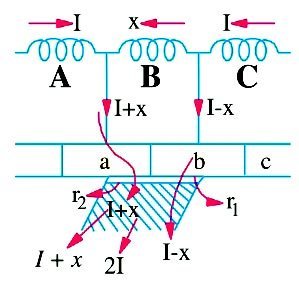
In DC generators, the brush width is greater than the width of a commutator segment and the mica insulation. The armature coils connected to the commutator segments become short-circuited during the spanning of the brush. Commutation is the process of collection of current by the brush or the changes that take place in a coil during the period of the short circuit by a brush. The induced current in the armature conductors of the DC generators is alternating in nature. The commutator is used to make their flow unidirectional. Method of Increasing short circuit There are three methods to Improve the commutation Resistance Commutation In this method, low-resistance copper brushes are replaced by comparatively high-resistance carbon brushes. From the above fig. it can be seen that the current I from coil C when passing through commutator segment ‘b’ has two parallel paths. One is straight from ‘b’ to brush while the other is through short-circuited coil B to segment ‘a’ and then to the brush. By using low resistance copper brush the current will not prefer the second path as it will prefer first low resistance path. When carbon brushes having comparatively high resistance are used then current I through coil C will select the second path as resistance r1 of the first path will be increasing due to decrease in contact area of ‘b with brush and resistance r2 of second path will be decreasing due to increase in contact area of ‘a’ with brush. If carbon brushes are used, current will follow the second path instead of the first path for the following reasons: (i) The resistance of the first path increases because the area of contact of bar “b” diminishes. (ii) The resistance of the second path decreases because of the area of contact of the bar “a” increases. Carbon brushes have the following advantages: (i) Their high contact resistance is useful for good commutation. (ii) They lubricate and polish the commutator during rotation. (iii) In spite of sparking, carbon brushes cause less damage to the commutator as compared to copper brushes. Carbon brushes have the following disadvantages: (i) They are more suitable for small machines because a contact drop of 2 V occurs due to their high contact resistance. (ii) The commutator needs to be made larger than the copper brushes due to the loss of contact drop. (iii) Large brush holders are required due to their lower current density. E.M.F Commutation:- In this method, the arrangement is made to neutralize the reactance voltage by producing a reversing e.m.f. in the short-circuited coil under commutation. This reversing e.m.f., as the name shows, is an e.m.f. in opposition to the reactance voltage and if its value is made equal to the latter, it will completely wipe it off, thereby producing the quick reversal of current in the short-circuited coil which will result in sparkless commutation. The reversing e.m.f. may be produced in two ways: (i) either by giving the brushes a forward lead sufficient enough to bring the short-circuited coil under the influence of the next pole of opposite polarity or (ii) by using interpoles. Compensating Winding The compensating winding in a DC motor serves the purpose to reduce armature reaction. Also, they prevent the main field to the crowd in one side. These are series coils that are placed in the slots of poles coinciding with the axis of brushes in the motor. They are connected to the armature in series. The magnetic field is produced by these series connected windings, which vary according to the armature current. These compensating windings arc wound so that they can neutralize the effects generated by the field of the armature. To give speed in commutation process the reactance voltage should be neutralized and this is done by injecting the suitable polarity dynamical voltage into commutating coil. Compensating windings are used to overcome the commutation and cross-magnetization of armature reaction, which causes high flux density in trailing pole tip. Also, the coil under this tip can develop the induced voltage that is high enough to cause a flashover between nearby commutator segments. Physically, this coil is much closer to the commutation zone in which the air temperature can be high due to the commutation process. Therefore, the compensating windings are located on pole shoe to avoid flashover.
Ques.139. The synchronous generator can operate at:-
- Lagging power factor only
- Lagging, leading and unity power factor✓
- Leading power factor
- None of these
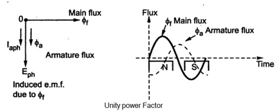
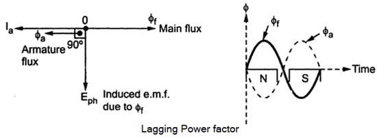
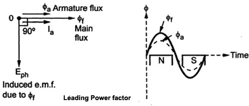
Armature Reaction When the load is connected to the alternator, the armature winding of the alternator carries a current. Every current carrying conductor produces its own flux so armature of the alternator also produces its own flux when carrying a current. So there are two fluxes present in the air gap, one due to armature current while second is produced by the field winding called main flux. The flux produced by the armature is called armature flux So the effect of the armature flux on the main flux affecting its value and the distribution called armature reaction. The effect of the armature flux not only depends on the magnitude of the current flowing through the armature winding but also depends on the nature of the power factor of the load connected to the alternator Consider a purely resistive load connected to the alternator, having unity power factor. As induced e.m.f Eph drives a current Iph and load power factor is unity, EphandIphare in phase with each other. If φf is the main flux produced by the field winding responsible for producing Ephthen Eph lags φf by 90°. Now current through armature Ia produces the armature flux say to,, So flux φa, and la are always in the same direction. It can be seen from the phasor diagram that there exists a phase difference of 90°between the armature flux and the main flux. From the waveforms, it can be seen that the two fluxes oppose each other on the left half of each pole while assist each other on the right half of each pole. Hence average flux in the air gap remains constant but its distribution gets distorted. Hence such distorting effect of armature reaction under unity p.f. the condition of the load is called the cross magnetizing effect of armature reaction. Due to such distortion of the flux, there is the small drop in the terminal. Consider a purely inductive load connected to the alternator having zero lagging power factor. This indicates that Iph driven by Eph lags Eph by 90° which is the power factor angled. Induced e.m.f. Eph lags main fluxes φf by 90° while φa is in the same direction as that of Ia. It can be seen from the phasor diagram that the armature flux and the main flux art exactly in opposite direction to each other. So armature flux tries to cancel the main flux Such an effect of armature reaction is called the demagnetizing effect of the armature reaction. As this effect causes the reduction in the main flux, the terminal voltage drops. This drop in the terminal voltage is more Man the drop corresponding to the unity p.f. load. Consider a purely capacitive load connected to the alternator having zero leading power factor. This means that armature current Iaph driven by Eph leads Eph by 90° which is the power factor angle φ. Induced e.m.f. Eph lags φf by 90° while Iaph and φa, are always in the same direction. The armature flux and the main field flux are in the same direction i.e. they are helping each other. This results in the addition in main flux. Such an effect each armature reaction due to which armature flux assists field flux is called the magnetizing effect of the armature reaction As this effect adds the flux to the main flux, greater e.m.f. gets induced in the armature Hence there is an increase in the terminal voltage for leading power factor loads.Unity Power Factor Load (Cross-Magnetizing)
Zero Lagging Power Factor Load (Demagnetizing)(Over-excited)
Zero Leading Power Factor Load (Magnetizing) Under-excited
Ques.140. Which instrument is used to detect the small electric current?
- Voltmeter
- Wattmeter
- Multimeter
- Galvanometer✓
A galvanometer is an instrument which is used to detect the presence and measure magnitude of the small currents or voltages in the measuring circuits. Thus galvanometer term is generally used for any current or voltage indicating instruments which are not calibrated. The galvanometers are most widely used for detecting the presence of a current in the circuit. But mainly galvanometers are used to indicate zero current in bridge and potentiometer circuits. In most of the measurement techniques, the circuit adjusted for zero current or zero deflection of galvanometer which is commonly called Null on the galvanometer. In many applications, it is necessary to detect the smallest current in the circuit. This purpose is fulfilled by the galvanometer which gives readable, significant deflection for the smallest current. Thus the galvanometer should have sufficient sensitivity. Apart from this important factor, it should have stable zero and short periodic time.

