Ques.141. According to Fleming’s right-hand rule, what does the thumb indicate?
Direction of the motion of the conductor relative to the magnetic field✓
Direction of the induced or generated Current with the conductor
Direction of the magnetic field
None of these
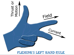
Fleming’s left-hand rule.
When a current carrying conductor such as a wire attached to a circuit moves placed in a magnetic field, an electric current is induced in the wire due to Faraday’s law of induction.
The right hand is held with the thumb, first finger and second finger mutually perpendicular to each other than
The thumb is pointed in the direction of the motion of the conductor relative to the magnetic field i.e direction of the force.
The forefinger is pointed in the direction of the magnetic field.
The middle finger represents the direction of the induced or generated current within the conductor.
Ques.142. dv/dt protection is provided to the SCR by:-
Connecting a capacitor & resistor in parallel with the device✓
Connecting a capacitor in parallel with the load
Connecting an inductor in series with the load
Connecting an inductor & resistor in parallel with the device
Thyristor protection or SCR Protection
The transient overvoltages can switch on the thyristor. In some cases, the thyristor can be damaged due to these transient voltages. These transient voltages are very common when the converter is having inductive loads.
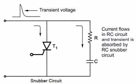
Snubber circuit: The thyristors can be protected against transient voltages by an RC network This RC network is connected in parallel across the thyristor. It is called snubber circuit.
The Fig. shows snubber(RC) circuit. The resistance has the value of few hundred ohms. Whenever there is a large spike or voltage transient across the thyristor, it is absorbed by the RC circuit. The RC circuit (snubber) acts as a lowpass filter for this voltage transient.A low-pass filter (LPF) is a filter that passes signals with a frequency lower than a certain cutoff frequency and attenuates signals with frequencies higher than the cutoff frequency.
The resistance has normally low value so that the transient is absorbed by the capacitor quickly. Thus the thyristor is protected against voltage transients. The RC snubber circuit very commonly used for protection of thyristors against transient voltage High-frequency voltage spikes).
Ques.143. Consider the two transistor analogy of SCR, if α1 & α2 are the common-base current gain of both the transistors then to turn-on the device:-
α1 − α2 should approach zero
α1 + α2 should approach zero
α1 + α2 should approach Unity✓
α1 × α2 should approach zero
SCR is a unidirectional device and like a diode, it allows current to flow in one direction only. It can be used as a switch. The switching of SCR is controlled by the additional input called gate and biasing conditions. It can be used as a rectifier to convert AC signals to DC signals.
Construction
The SCR is a four-layer p-n-p-n device, where p and n layers are alternately arranged. The outer layers are heavily doped. There are three p-n junctions called J1, J2, and J3. The outer P-layer is called anode and outer n-layer is called cathode, middle P-layer is called the gate. The terminals are taken out from their layers. Anode must be positive with respect to the cathode so that SCR will be forward biased. To turn on an SCR, a current is to be passed through the gate terminal. Hence it is a current operated device.
Two Transistor Model of SCR
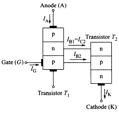
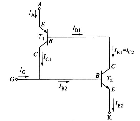
The operation of an SCR can also be explained in a very simple way by considering it in terms of two transistors. This is known as the two transistor analogy of the SCR. The SCR can be considered as an NPN and a PNP transistor, where the collector of one transistor is attached to the base of the other and vice versa. This model is obtained by splitting the two middle layers of the SCR into two separate parts.
In the above figure, two middle layers of the SCR is split into two separate parts i.e PNP transistor T1 and NPN transistor T2. The collector terminal of NPN transistor T2 drives the base of the upper transistor PNP T1, while the collector terminal of PNP transistor T1 drives the base of NPN transistor T2.
The relation between the anode current and the current gain of transistor t1 and t2 is given as
Ia = (α2Ig) ⁄ [1 − (α1 + α2)
Where
Ia = Anode current
Ig = Gate current
α1 = Current gain of transistor t1
α2 = Current gain of transistor t2
From the above, equation if, (α1 + α2) = 1, then anode current becomes infinite, i.e. it suddenly attains very high value approaching infinity. The device latches into conduction (ON) state from nonconducting (OFF) state. This action of SCR is called the regenerative action. As the gate current IG is of such a value that (α1 + α2) approaches unity, the SCR gets turned on.
Ques.144. Carborundum is also known as:-
Silicon Carbide✓
Germanium
Lead sulfide
Gallium arsenide
Carborundum is also known as silicon carbide and it is used to make varistor.
Ques.145. The constant speed of a synchronous motor can be changed to new fixed value by which of the following methods?
By changing the applied voltage
By changing the supply frequency✓
By interchanging the two phases
All of the above
The speed of the synchronous motor is given as
Ns = 120f/P
So the speed of the synchronous motor can be changed by changing either the number of poles or the frequency.
Ques.146. Constantan is an alloy which contains ______metals.
Silver and Tin
Copper and Tungsten
Copper and Nickel✓
Copper and ZInc
Constantan: Constantan is a copper alloy containing 40 percent nickel, 1.5 percent manganese, and the rest copper. The main feature of Constantan: is its high electrical resistivity which remains almost constant upon variations in temperature. Constantan is used for rheostats, therms couples and heating devices operating at moderately high temperatures.
Note:-
Brass is a metallic alloy that is made of copper and zinc.
Tin-silver-copper (SnAgCu, also known as SAC), is a lead-free (Pb-free) alloy commonly used for electronic solder
Ques.147. Thermoelectric cooling systems make use of which effect to create a heat flux between the junction of two different types of materials?
Peltier effect✓
Reuters Effect
Seebeck Effect
None of these
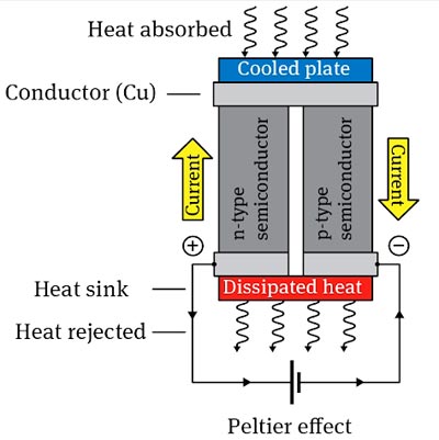
Peltier Effect
In 1834, Jean Charles Athanase Peltier, a French watchmaker turned scientist discovered the thermoelectric effect which is the converse of the Seebeck effect. He discovered that when current is passed through the junction between two conductors, heat is either evolved or absorbed. When the direction of the current is the heating effect is also reversed.
The absorption or evolution of heat at a junction of two dissimilar metals when current is passed is known as Peltier effect.
Thermoelectric cooling uses the Peltier effect to create a heat flux between the junctions of two different types of solid materials. This effect relates to the energy transfer at the junction of two dissimilar materials when the electric current is passing through it. When the junction is maintained at a given temperature an equivalent heat addition or heat removal is present, so-called the Peltier heat, which is reversible and proportional to the electric current. Semiconductor materials are most often used as thermoelectric elements. This effect is commonly used in camping and portable coolers and for cooling electronic components and small instruments. The thermoelectric device is characteristic for the lack of moving parts and is easily controlled and reversible.
Ques.148. Calculate the scale span of the instrument that is calibrated between 20 bar and 200 bar and used for the measurement of pressure.
20 bar
180 bar✓
190 bar
220 bar
Span is defined as the algebraic difference between the upper and lower range values.
Upper Limit = 200 bar
Lower Limit = 20 bar
Span = 200 − 20 = 180 bar
Ques.149. Calculate the current (in Ampers) flowing in the conductor when 5 × 10¹⁹ electrons are flowing per second through it.
5
3
8✓
1.6
When 1 Coulomb charge flows through a wire in 1 second then the current through the wire is 1 AMPERE.
I = Q/T
Where I is current in A
Q is the charge and t is the time.
1 electron has a charge of 1.6 × 10⁻¹⁹ Coulombs of charge.
so 5 × 10¹⁹ electrons has a charge of 5 × 1019 × 1.6 × 10−19 = 8 coulomb
Current I = Q/T = 8/1 = 8 Ampere
Ques.150. Calculate the gauge factor of a strain gauge, if the value of resistance is 152 Ohms, which changes by 5 Ohms for 5000 microstrain.
5.58
6.58✓
3.68
4.59
Gauge factor (GF) or strain factor of a strain gauge is the ratio of relative change in electrical resistance R, to the mechanical strain ε.
GF=change in resistance/(resistance × strain)
Change in resistance = 5 ohm
Resistance = 152 Ohms
Strain = 5000 microstrain = 5 × 10⁻³
Gauge factor = 5/(152 × 5 × 10−3)
Gauge factor = 6.58
For UPPCL JE 2016 Electrical paper with complete solutionClick Here
For UPPCL JE 2016(Evening Shift) Electrical paper with complete solutionClick Here