
Ques.21. The binary code of (10.625)_10 is:-
- (1010.101)_2 ⁄ (1010.101)_2✓
- (1010.100)_2 ⁄ (1010.100)_2
- (1010.111)_2 ⁄ (1010.111)_2
- (1010.010)_2 ⁄ (1010.010)_2
First, convert to binary (base 2) the integer part: 10. Divide the number repeatedly by 2, keeping track of each remainder, until we get a quotient that is equal to zero: division = quotient + remainder; 10 ÷ 2 = 5 + 0; 2. Construct the base 2 representation of the integer part of the number, by taking all the remainders starting from the bottom of the list constructed above: 3. Convert to binary (base 2) the fractional part: 0.625. Multiply it repeatedly by 2, keeping track of each integer part of the results, until we get a fractional part that is equal to zero: multiplying = integer + fractional part; 4. Construct the base 2 representation of the fractional part of the number, by taking all the integer parts of the multiplying operations, starting from the top of the constructed list above: Positive number before normalization: 10.625(10) = 1010.101(2)
5 ÷ 2 = 2 + 1;
2 ÷ 2 = 1 + 0;
1 ÷ 2 = 0 + 1;
10(10) = 1010(2)
1) 0.625 × 2 = 1 + 0.25;
2) 0.25 × 2 = 0 + 0.5;
3) 0.5 × 2 = 1 + 0;
0.625(10) = 0.101(2)
Ques.22. The steam engine is based upon which of the following thermodynamic cycles?
- Rankine cycle✓
- Brayton cycle
- Stirling cycle
- Carnot cycle
The Rankine cycle is a model used to predict the performance of steam turbine systems. It was also used to study the performance of reciprocating steam engines. The Rankine cycle is an idealized thermodynamic cycle of a heat engine that converts heat into mechanical work while undergoing the phase change. The heat is supplied externally to a closed loop, which usually uses water as the working fluid. It is named after William John Macquorn Rankine, a Scottish polymath and Glasgow University professor. Power depends on the temperature difference between a heat source and a cold source. The higher the difference, the more mechanical power can be efficiently extracted out of heat energy, as per Carnot’s theorem. The heat sources used in these power plants are usually nuclear fission or the combustion of fossil fuels such as coal, natural gas, and oil, or concentrated solar power. The higher the temperature, the better. Principal Components of Vapour Power Plant The four basic components of a vapor power plant are shown in Fig. Each component in the cycle is regarded as a control volume, operating at steady state. Brayton Cycle:- The Brayton cycle is the ideal cycle for gas-turbine engines. Today, it is used for the gas turbine in which both the compression and expansion processes are implemented such as the jet engine. Stirling cycle:- Stirling engine is used in some submarines because this engine produces very less noise thus serving its purpose for the submarine which is used for secret purposes. it is also used in automobile, aircraft engines, pump engine etc. Carnot cycle:- Carnot engine is a theoretical cycle. It is used for analytical and more importantly reference purposes only.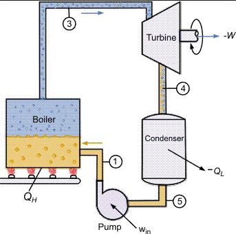
Ques.23. The effective turning off SCR after the anode current has reached zero value.
- The charge is removed by applying reverse anode-cathode voltage✓
- Chargers are injected by applying reverse anode-cathode voltage
- Chargers are injected by applying the gate signal
- None of these
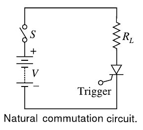
Normal thyristors (silicon-controlled rectifiers) are not fully controllable switches (a “fully controllable switch” can be turned on and off at will). Thyristors can only be turned ON using the gate lead, but cannot be turned OFF using the gate lead. Thyristors are switched ON by a gate signal, but even after the gate signal is de-asserted (removed), the thyristor remains in the ON-state until a turn-off condition occurs (which can be the application of a reverse voltage to the terminals or a decrease of the forward current below a certain threshold value known as the “holding current”). Thus, a thyristor behaves like a normal semiconductor diode after it is turned on or “fired”. The term commutation basically means the transfer of current from one path to another. Commutation is one of the fundamental principles the use of thyristors for control purposes. A thyristor can only operate in two modes: it is either in the OFF state, i.e., open circuit, or in the ON state, i.e., short circuit. By itself, it cannot control the level of current or voltage in a circuit. Control can only be achieved by variation in He time thyristors when switched ON and OFF, and commutation is central to this switching process. There are three methods of switching off the SCR, namely natural commutation, reverse bias turn-off, and gate turn-off. When the anode current is reduced below the level of the holding current, the SCR turns off. However, it must be noted that rated anode current is usually larger than 1,000 times the holding value. Since the anode voltage remains positive with respect to the cathode in a dc circuit, the anode current can only be reduced by opening the line switch S, increasing the load impedance RL or shunting part of the load current through a circuit parallel to the SCR, i.e. short-circuiting the device. (b) Reverse-bias Turn-off A reverse anode to cathode voltage (the cathode is positive with respect to the anode) will tend to interrupt the anode current. The voltage reverses every half cycle in an ac circuit so that an SCR in the line would be reverse biased every negative cycle and would turn off. This is called phase commutation or ac line commutation. To create a reverse biased voltage across the SCR, which is in the line of a dc circuit, capacitors can be used. The method of discharging a capacitor in parallel with an SCR to turn-off the SCR is called forced commutation. In power electronic applications one advantage of using SCRs is that they are compact. The control equipment is also compact if integrated circuits are used. There has also been an attempt to miniaturize capacitors used for forced commutation and for filtering. The former use is important because the currents can be high and thermal dissipation takes high priority in design considerations. Small sizes of capacitors are at present being achieved by the use of metalized plastic film or a plastic film and aluminum foil. In some specially designed SCRs, the characteristics are such that a negative gate current increases the holding current so that it exceeds the load current and the device turns-off. The current ratings are presently below 10 A and this type will not be considered further.Natural Commutation
(c) Gate Turn Off
Ques.24. Why regenerator used in the gas turbine power plant?
- To produce extra heat
- To produce the high pressure in the chamber
- To produce high temperature
- To recover heat from exhaust gases✓
Gas turbine plants are used for power generation where fuel oil is cheap, water scarce, natural gas available and the load factor very low, in the range of 15% to 18%. Waste heat during the working of gas turbines in the process of combustion can be used for the production of producer gas and for district heating. Gas turbine stations can be used as standby plants. The plants can be located in cities and industrial centers in close proximity to areas having heavy electrical power demand. The efficiency of the simple gas turbine is very low. There are three methods to increase the thermal efficiency of the cycle, which are: regeneration, reheating and intercooling. Regeneration:- Recovering waste heat from the high-temperature exhaust gases of a gas turbine is a means of improving the cycle efficiency. It is similar to the air preheater in the case of thermal power plants. The device used for extracting the heat from the heated gas is called a regenerator or heat exchanger. These are either tabular or rotary plate type in construction. The figure shows a line diagram of the gas turbine with regenerator. The use of a regenerator in a gas turbine presents three problems: necessity of large area of tube surface, maintenance of clean surfaces, and increased resistance flow. The effectiveness of a regenerator is transferring all the energy available from the exhaust gases to the air, which is to be heated. Reheating:- Partially expanded high-temperature gas in the turbine can be reheated so that it can be expanded further to produce additional work. There may be several stages of heating. If only one turbine is there, then there will be no use of reheating. In the two-stage turbine, one reheater can be used, as shown in Figure 8.4. It improves the performance of the gas turbine plant. Intercooling:- Compressor consumes very high energy and therefore two compressors are used with intercooling, which acts as a heat exchanger, as shown in Figure 8.5. The power required to run the compressor could be reduced because of a reduction in the volume of air-cooled. The number of stages of compressors is decided based on the cost and energy saving. Intercooling results in the enhancement of thermal efficiency, air rate, and work ratio. Therefore, the overall size of the power plant is reduced for the same capacity. Normally, air or water is used to cool the compressor.
Ques.25. Identify the ways by Which the cost of Power Generation can be reduced?
1.1. Reduce the amount of investment in the plant
1.2. Reduce the power generation to match costs.
2.1. Reduce the amount of investment in the plant
2.2. Reduces the number of the man employed in the plant
3.1. Choosing equipment that is cheaper though it may not be efficient
3.2. Reduce the cost of labor and fuel
4.1. Select the station as reduced cost of fuel, labor, etc.
4.2. Produce minimum power at a given point of time✓
Cost of Electrical Energy The total cost of electrical energy generated can be divided into three parts, namely; Fixed cost:- It is the cost which is independent of maximum demand and units generated. The fixed cost is due to the annual cost of central organization, interest on the capital cost of land and salaries of high officials. The capital cost of building central station generators vary from region to region, largely as a function of labor costs and “regulatory costs,” which include things like obtaining siting permits, environmental approvals, and so on. Further, the capital investment on the land is fixed and hence the amount of interest is also fixed. Semi-fixed cost: It is the cost which depends upon maximum demand but is independent of units generated. The semi-fixed cost is directly proportional to the maximum demand on the power station and is on account of annual interest and depreciation on capital investment of building and equipment, taxes, salaries of management and clerical staff. The maximum demand on the power station determines its size and cost of installation. The greater the maximum demand for a power station, the greater is its size and cost of installation. Further, the taxes and clerical staff depend upon the size of the plant and hence upon maximum demand. Running costs:- It is the cost which depends only on the number of units generated. The running cost is on account of the annual cost of fuel, lubricating oil, maintenance, repairs and salaries of operating staff. Since these charges depend upon the energy output, the running cost is directly proportional to the number of units generated by the station. In other words, if the power station generates more units, it will have a higher running cost and vice-versa. The cost of fuel is a very important consideration as it is the one cost that is directly and immediately reflected in the product. In a fossil-fueled power plant, the chemical energy in the fuel is converted to electrical energy at an efficiency determined by the design of the plant. The cost of the fuel, therefore, becomes a known fraction of the cost of electricity. Power utilities thus preferentially operate those plants which have high efficiencies and low fuel costs so as to minimize the fraction of fuel cost in the overall cost of producing electricity. Irrespective of technology, all generators share the following characteristics which influence the plant’s operations: The minimum run time and ramp times determine how flexible the generation source is; these vary greatly among types of plants and are a function of regulations, type of fuel, and technology. Generally speaking, plants that are less flexible (longer minimum run times and slower ramp times) serve base load energy, while plants that are more flexible (shorter minimum run times and quicker ramp times) are better-suited to filling peak demand. It is important to realize that, in some sense, these are “soft” constraints. It is possible, for example, to run a nuclear plant for five hours and then shut it down. Doing this, however, imposes a large cost in the form of wear and tear on the plant’s components
This variable influences how quickly the plant can increase or decrease power output, in [MW/h] or in [% of capacity per unit time]
The amount of time it takes from the moment a generator is turned on to the moment it can start providing energy to the grid at its lower operating limit (see below), in [h]
The maximum output of a plant, in [MW]
The minimum amount of power a plant can generate once it is turned on, in [MW]
The shortest amount of time a plant can operate once it is turned on, in [h].
The cost of turning the plant on, but keeping it “spinning,” ready to increase power output, in [$/MWh]. Another way of looking at the no-load cost is the fixed cost of operation; i.e., the cost incurred by the generator that is independent of the amount of energy generated.
These are the costs involved in turning the plant on and off, in [$/MWh].
Ques.26. What are the gates needed to make a half adder circuit?
- EX-OR gates and AND gate✓
- EX-OR gates and OR gate
- EX-NOR gates and NAND gate
- EX-NOR gates and NOR gate
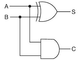
An adder circuit is a combinational digital circuit that is used for adding two numbers. A typical adder circuit produces a sum bit (denoted by S) and a carry bit (denoted by C) as the output. The basic operation of an adder circuit is to add two binary digits. It consists of four different possibilities as (0+0), (0+1), (1+0), and (1+1). The result of the addition is shown below for the two bits X and Y. We find that except for the last combination, the first three combinations are the same as decimal addition. For the last combination, we know that (1+1) = 2 in decimal addition and the binary equivalent of 2 is (10)2 in base 2. For the result 102, the digit under Unit’s place is ‘0’ and ‘1’ is carried forward to the Ten’s place. The truth table for adding two binary digits is shown on the right. In the table, X and Y represent the two binary digits, S represents the sum and C represents any carry forward. We can see that the sum is 0 when both the digits are zero or when both the digits are 1. The sum bit is 1 only when either of the input digits is 1. The carry output is 1 only when both the inputs are 1. If A and B are the input bits, then sum bit (S) is the X-OR of A and B and the carry bit (C) will be the AND of A and B. From this, it is clear that a half adder circuit can be easily constructed using one X-OR gate and one AND gate. A half adder is the simplest of all adder circuit, but it has a major disadvantage. The half adder can add only two input bits (A and B) and has nothing to do with the carry if there is any in the input. So if the input to a half adder has a carry, then it will be neglected it and adds only the A and B bits. Meaning if you add 1+1, it gives 0 and not 10 (which is the binary equivalent of 2) So, in that sense, a half-adder is ‘incomplete’ and that is the disadvantage. Note:- A half-adder can also be realized in universal logic by using either only NAND gates or only NOR gates.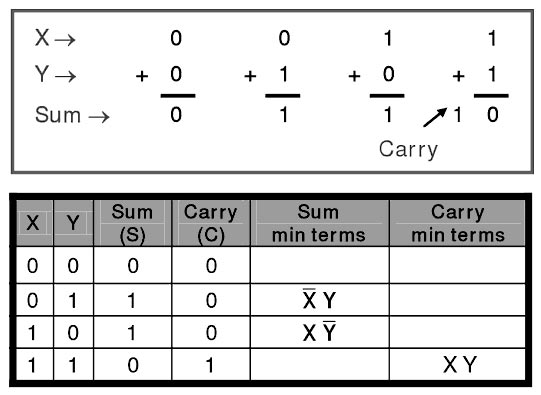
Ques.27. What will be the rotation speed of a 3-phase, 4-pole, 50 Hz synchronous motor, if the frequency number of poles and load torque is halved?
- 3000 RPM
- 750 RPM
- 6000 RPM
- 1500 RPM✓
Synchronous speed of the Motor is given as Ns = 120f/P Ns = 120 x 50/4 = 1500 RPM
Ques.28. Welding generator can produce
- Both AC and DC✓
- DC only
- AC only
- None of these
Generators and alternators both produce welding electricity from a mechanical power source. Both devices have an armature that rotates and a stator that is stationary. As a wire moves through a magnetic force field, electrons in the wire are made to move, producing electricity. In an alternator, magnetic lines of force rotate inside a coil of wire. An alternator can produce AC only. In a generator, a coil of wire rotates inside a magnetic force. A generator can produce AC or DC. It is possible for alternators and generators to both use diodes to change the AC to DC for welding. Internally, all generators produce an alternating voltage. There are several other primary differences between AC and DC generators. Some of them are listed below. Both AC and DC generators produce currents using electromagnetic induction. In AC generators, the coil through which the current flows is fixed, and the magnet is moving. The magnet’s north and south poles cause the current to flow in opposite directions, producing alternating current. With DC generators, the coil through which the current flows rotates in a fixed field. The two ends of the coil attached to a commutator, different halves of a single, rotating split ring. Metal brushes connect these split rings to an external circuit. The commutator balances the charges leaving and returning to the generator, resulting in a current that does not change direction. In generators, the welding current is produced on the armature and is picked up with brushes,. In alternators, the welding current is produced on the stator, and only the small current for the electromagnetic force field goes across the brushes. Therefore, the brushes in an alternator are smaller and last longer. Alternators can be smaller in size and lighter in weight than generators and still produce the same amount of power.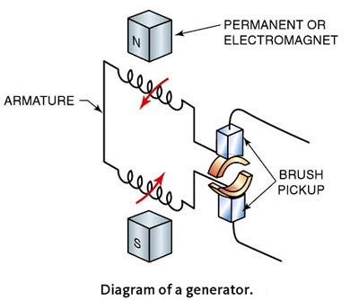
Ques.29. Water is decomposed into hydrogen and oxygen by means of an electric current by the method of
- Electrolysis✓
- Electric Heating
- Electroplating
- None of these
Electrolysis is a process of detaching or dissociating bonded elements and compounds by passing through them an electric current. Water electrolysis decomposes H2O into hydrogen and oxygen gas. Care must be taken in choosing the correct electrolytes, nominally substances that contain free ions and hence behave as an electrically conductive medium. Electrolytes dissolve and dissociate into cations Positive ions, +) and anions Negative ions, -) that carry the current. As we have seen in Chapter 2, such processes can occur in an electrolysis cell, or electrolyzer, which consists of two electrodes, cathode, an anode, where reduction and oxidation reactions simultaneously take place forming H2 (at the cathode) and O2 (at the anodes). 2H2O(l) → 2H2(g)+O2(g) – water decomposes into hydrogen and oxygen in the presence of an electric current; 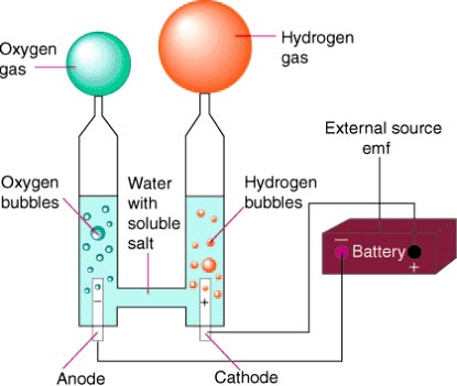
Ques.30. Which principle type of turbines is used in the hydroelectric power station?
- Impulse Type
- Reaction Type
- Both Impulse and Reaction type✓
- None of these
A turbine is a hydraulic machine which converts hydraulic energy into mechanical energy. Turbines are classified as given below: The impulse or Pelton wheel is generally used in plants with heads higher than 850 feet (260 meters), although some installations have lower heads. A reaction turbine is a type of turbine that develops torque by reacting to the pressure or weight of a fluid; the operation of reaction turbines is described by Newton’s third law of motion (Every action has an equal and opposite reaction). E.g of Reaction turbine is the Kaplan turbine, Propeller turbine, Francis turbine, Bulb turbine, Straflo, Tube turbine. Francis is the medium head turbine, while Kaplan is the low head turbine, Pelton is the high head turbine.

