
Ques.51. Magnetic disk, electric motors, speakers, relays use which of the following elements?
- Geothermal Energy
- Hydrochemical agents
- Electromagnets✓
- None of these
Electromagnets use electricity to create their power of magnetism. Electricity moving along the straight wire creates a magnetic field. This magnetic field gets weaker as it moves away from the wire. But if the wire is coiled, the magnetic field is forced back toward the wire and it becomes stronger. Electromagnets are made of coils of wire called as solenoids. A current through the wire creates a magnetic field which is concentrated in the hole in the center of the coil. The wire turns are often wound around a magnetic core made from a ferromagnetic or ferrimagnetic material such as iron; the magnetic core concentrates the magnetic flux and makes a more powerful magnet. The main advantage of an electromagnet over a permanent magnet is that the magnetic field can be quickly changed by controlling the amount of electric current in the winding. However, unlike a permanent magnet that needs no power, an electromagnet requires a continuous supply of current to maintain the magnetic field. Electromagnets are widely used as components of other electrical devices, such as motors, generators, electromechanical solenoids, relays, loudspeakers, hard disks, MRI machines, scientific instruments, and magnetic separation equipment. Electromagnets are also employed in the industry for picking up and moving heavy iron objects such as scrap iron and steel.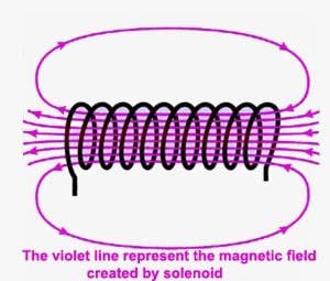
Ques.52. Quadrature axis synchronous reactance is the ration of
- Vmin to Imax✓
- Vmin to Imin
- Vmax to Imax
- Vmax to Imin
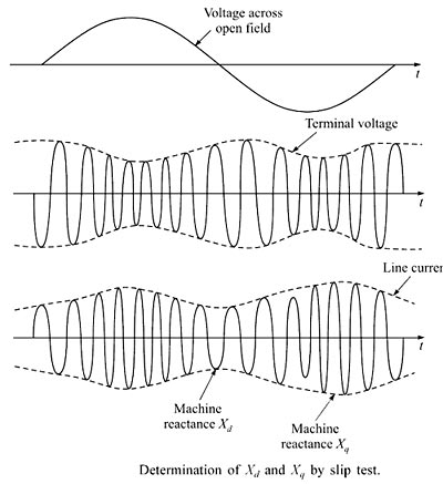
Direct-axis and Quadrature-axis The total mmf in a synchronous machine may be split up into two components—one along the pole axis or direct axis and the other at right angles to this or the quadrature axis. In the case of cylindrical rotor machines, the air gap is uniform and the reluctance of the magnetic circuit along both the axis is the same. The effect of armature reaction fluxes and the voltages induced constant for all the positions of field poles with respect to the armature. In the case of salient pole construction, however, the reluctances of the magnetic circuits on which the mmfs act are different along the direct axis and the quadrature axis. The reluctance of the direct axis magnetic circuit is due to the yoke and teeth of the stator, airgap, pole, and core of the rotor. In the quadrature axis, the reluctance is mainly due to the large airgap in the interpolar space. The armature currents produce the same fundamental mmf wave regardless of the angular, position of the rotor, but the fundamental flux varies with the rotor position. If the rotor is rotated that the pole axis or the direct axis stays in line with the crest of the rotating mmf, wave lo reluctance or high permeance is offered and the fundamental flux wave has its greatest magnitude for a given armature current. Air has more reluctance than any laminations of cast iron/silicon steel. It is clear that in d-axis, the air gap is less. If the air gap is less, the reluctance is low. Similarly, the air gap in the q-axis is more hence the reluctance is high. As the air gap is nonuniform, the reactance offered also varies and hence current drawn the armature also varies cyclically at twice the slip frequency. The r.m.s. current is minimum when machine reactance is Xd and it is maximum when machine reactance is Xq. As the reactance offered varies due to the non-uniform air gap, the voltage drops also varies cyclically. Hence the impedance of the alternator also varies cyclically. The terminal voltage also varies cyclically. The voltage at terminals is maximum when current and various drops are minimum while the voltage at terminals is minimum when current and various drops are maximum. The waveforms of the voltage induced in the rotor, terminal voltage and current drawn by armature are shown in the Figure below. The direct axis and the quadrature axis synchronous reactances can be defined as follows: The direct axis synchronous reactance is the ratio of the fundamental component of the reactive armature voltage due to the fundamental direct axis component of armature current to this component of current under steady-state conditions and at the rated frequency. Direct axis air gap between rotor and stator is less than that of the quadrature axis air gap, so the current required for magnetization is less in case of the direct axis. Xd=Vmax/Imin The quadrature axis synchronous reactance is the ratio of the fundamental component of reactive armature voltage due to the fundamental direct axis component of armature current to this component of current under steady-state conditions and at the rated frequency. When the rotor and stator rotating magnetic field aligns along with the quadrature axis, air gap reluctance is maximum. Therefore more magnetizing current is drawn by the stator to maintain the flux and the voltage is minimum.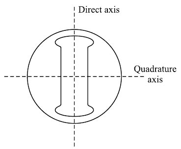
∴ Quadrature axis synchronous reactance Xq = Vmin / Imax.
Ques.53. Latching current for an SCR is 100 mA, a dc source of 200 V is also connected to the SCR which is supplying an R-L load. Compute the minimum width of the gate pulse required to turn on the device. Take L = 0.2 H & R = 20 ohm both in series.
- 81 μsec
- 62.7 μsec
- 100.5 μsec✓
- 56.9 μsec
Expression of current in RL circuit as shown in the figure is $\begin{array}{l}i(t) = \dfrac{V}{R}\left( {1 – {e^{ – t\frac{R}{L}}}} \right)\\\\100 \times {10^{ – 3}} = \dfrac{{200}}{{20}}\left( {1 – {e^{ – t\frac{{20}}{{0.5}}}}} \right)\end{array}$ Solving the value of t t = 100.5 μs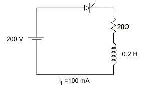
Ques.54. Stator and rotor fields rotate simultaneously in which of the following motors?
- Universal motor
- Synchronous Motor✓
- D.C Motor
- Reluctance Motor
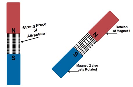
The synchronous motor is a truly constant speed motor. This is the specialty of this motor. Yet, it has very limited applications. To develop a steady torque, its rotor must be rotating at synchronous speed, Ns. This is the major defect of synchronous motors. Either it runs at synchronous speed, or it does not run at all. The stator field rotates at synchronous speed due to the three-phase currents supplied to its windings. In order to develop a continuous unidirectional torque, it is necessary that the stator and rotor poles do not move with respect to each other. This is possible only if the rotor also rotates at the synchronous speed. Therefore Magnetic Locking between the poles is necessary to do so. The concept of Magnetic Locking For magnetic locking condition, there must be two unlike poles and magnetic axes of this two poles must be brought very nearer to each other. At zero speed or at any other speed lower than synchronous speed, the rotor poles rotate slower than the stator field. Therefore, in one cycle of rotation of the stator field, the N-pole of the rotor is for some time nearer to N pole of the stator and for some other time nearer to the S-pole of the stator. As a result, the torque developed is for some time clockwise and for some other time anticlockwise. Consequently, the average torque developed remains zero. Hence the Synchronous Motor Run either on Synchronous Speed Or Not at all.
![]()
Where f = supply frequency
P = Number of poles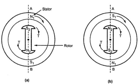
Ques.55. What does the Eddy current loss depend on?
- Frequency
- Thickness
- Flux density
- All of these✓
Eddy current loss: In transformer we provide alternating current in primary which produces alternating flux in core ,this flux links with secondary of transformer and induces emf in secondary, it may be possible that flux also links with some other conducting parts of transformer such as ferromagnetic core or iron body and induces local emf in these parts of transformer which will cause a circulating current to flow in these parts causing heat loss. these currents are called eddy current and this loss is called eddy current loss. Eddy current losses in the transformer are given by Eddy current losses = Ke × Bm2 × f2 × V ×t2 Where
Ke = Eddy current constant
t = thickness of the core
V = Volume of material
Bm = Maximum flux density
f = frequency
Ques.56. In which of the following conditions will a 3-phase synchronous machine work as a capacitor?
- Critically Excited
- Under Excited
- Over Excited✓
- None of the above
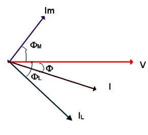
Synchronous condenser or capacitor A synchronous condenser is a synchronous motor running without the mechanical load. The Synchronous motor takes a leading current when over-excited and therefore behave as a capacitor. When such a machine is connected in parallel with the supply, it takes a leading current which partly neutralizes the lagging reactive component of the load. Thus the power factor is improved. Now let V is the voltage applied and IL is the current lagging V by angle φL. This power factor φL, is very low, lagging. The synchronous motor acting as a synchronous condenser is now connected across the same supply. This draws a leading current of Im. The total current drawn from the supply is now phasor sum of IL and Im. This total current I now lags V by smaller angle φ due to which effective power factor gets improved. This is how the synchronous motor as a synchronous condenser is used to improve the power factor of the combined load. Advantages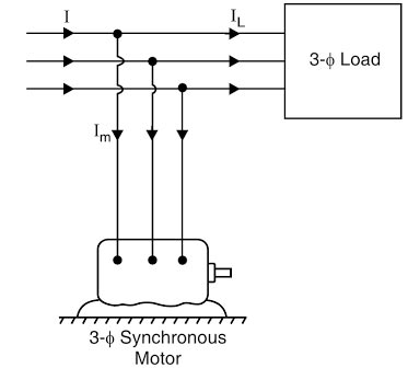
Ques.57. In which of the following magnetism types, the atoms are aligned in parallel magnetic moments?
- Ferro-magnetism✓
- Dia-magnetism
- Ferri-magnetism
- Para-magnetism
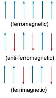
Ferromagnetic materials the most useful magnetic materials. These derive their name from iron (Ferrum) as the most common of the ferromagnetic materials. The relative permeability of ferromagnetic materials is much larger than 1 and can be in the thousands or higher. Some typical ferromagnetic materials are iron, cobalt, and nickel. Ferromagnetic materials tend to magnetize in the direction of the magnetic field and some of them retain this magnetize lion after the external magnetic field has been removed. When they do so, and the magnetization is permanently retained, the material becomes a permanent magnet. An additional important property of ferromagnetic materials is the dependence o magnetization on the level of the external field. Thus, magnetization in ferromagnetic materials is a nonlinear process. When a ferromagnetic substance is kept in the magnetic field, the permanent alignment of the domain due to a strong interaction (force) takes place between adjacent atoms in regions called magnetic domains. In these domains, large numbers of atoms are aligned parallel to each other so that the magnetic force within the domain is strong. When a ferromagnetic material is in the unmagnetized state, the domains are nearly randomly organized and the net magnetic field is zero. ANTI-FERROMAGNETIC MATERIALS If the alignment of the dipoles is compensatory so as to give zero net moments, the material is termed anti-ferromagnetic. Such a phenomenon is termed anti-ferromagnetism ). For example, MnO is anti-ferromagnetic. FERRIMAGNETIC MATERIALS When the magnetic dipoles are oriented in the parallel and antiparallel direction in unequal numbers, so that there is a net magnetic moment, ferrimagnetism is observed. All ferromagnetic, anti-ferromagnetic and ferrimagnetic substances transform to the paramagnetic material at certain characteristic temperatures. This happens due to the randomization of the spins at higher temperatures.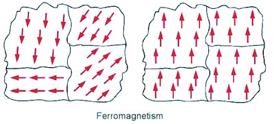
Ques.58. If the true power is 120 W and the power factor is 0.68, then what will be the apparent power ( in VA)?
- 81.6
- 17.6
- 176.47✓
- 103.2
The power triangle or Impedance triangle of the AC circuit is shown Below Cosφ = Base ⁄ Hypotenuse = Active Power ⁄ Apparent Power Active Power = Apparent power × Cosφ Apparent Power = Active Power/Cosφ Active Power = 120 W Power factor = 0.68 Apparent Power = 120/0.68 = 176.47 VA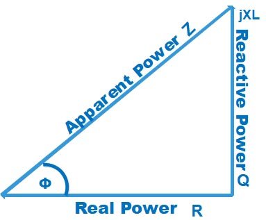
Ques.59. If the candle power is 45cd, then how much flux will be emitted by this source?
- 565.2 lumens✓
- 764 lumens
- 0.00725 lumens
- 9.20 lumens
Luminous flux of the lamp F = 4πL Where L = Luminous Intensity in candela F = 4 × π × L ( taking π = 3.14) F = (4 × 45 × 3.14) = 565.2 Lumen
Ques.60. The storage capacity of a SONY PENDRIVE is 16 GB. Here what does GB means in 16 GB?
- 1024 KB
- 1024 TB
- 1025 PB
- 1024 MB✓
GB stands for Gigabyte and 1 Gigabyte is equal to 1024 MB

