
Ques.71. What is the role of an alternator in a steam power station?
- It converts electric energy into mechanical energy
- It converts heat energy into mechanical energy
- It converts heat energy to electrical energy
- It converts mechanical energy into electrical energy✓
A generating station which converts heat energy (mechanical energy) of coal combustion into electrical energy is known as a steam power station. A steam power station basically works on the Rankine cycle. Steam is produced in the boiler by utilizing the heat of coal combustion. The steam is then expanded in the prime mover (i.e., steam turbine) and is condensed in a condenser to be fed into the boiler again. The steam turbine drives the alternator which converts the mechanical energy of the turbine into electrical energy. This type of power station is suitable where coal and water are available in abundance and a large amount of electric power is to be generated. For generating the electricity using the steam turbine, high-speed synchronous generators al used because the efficiency of steam turbines is high at high speed. Since the speed of turbo alternator is high, the diameters of the machine are kept minimum so that the centrifugal fort acting on the rotor is minimized. To keep the same electrical loading (which is proportional area x length), the length of the turbo-alternators is increased.
Ques.72. What is the principle of induction heating process?
- Nuclear heating principle
- Thermal ion release principle
- Resistance heating principle
- Electro-magnetic induction Principle✓
Induction heating is defined as the process of heating an electrically conducting object (usually a metal) by electromagnetic induction, through heat generated in the object by eddy currents. In induction heating when an alternating voltage applied to an induction coil (e.g., solenoid coil) will result in an alternating current in the coil circuit. An alternating coil current will produce in its surroundings a time-variable magnetic field that has the same frequency as the coil current. That magnetic field strength depends on the current flowing in the induction coil, the coil geometry, and the distance from the coil. The changing magnetic field induces eddy currents in the workpiece located inside the coil. These induced currents have the same frequency as the coil current; however, their direction is opposite to the coil current. Alternating eddy currents induced in the workpiece produce their own magnetic fields, which have opposite directions to the direction of the main magnetic field of the coil. Therefore, the total magnetic field of the induction coil is a result of the source magnetic field and induced magnetic fields. Alternating eddy currents produce heat by the Joule effect (I2R). A conventional induction heating system that consists of a cylindrical load surrounded by a multiturn induction, the coil is shown in Figure. In a narrow sense, induction heating is similar to the Joule heating effect, but with one important modification. The currents that heat the material are induced via electromagnetic induction. Therefore, it could be a non-contact heating process. Accordingly, only those with high electric conductivity, such as copper, gold, and aluminum, can be directly heated via induction. Food items are then heated by the metals. Induction heating works better on specific metals due to additional heating mechanisms. For instance, induction can heat ferrous metals better than other materials. That is because the iron crystals in ferrous metals can be repeatedly magnetized and demagnetized by the alternating magnetic field. This will lead to hysteresis losses in addition to the normal induction heating.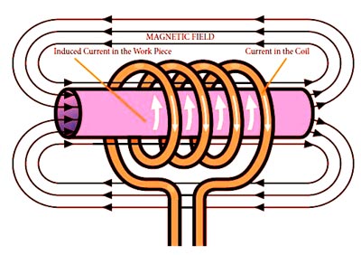
Ques.73. What is the number of the nodal equation in the nodal analysis of a linear circuit having 4 nodes?
- 6
- 5
- 4
- 3✓
The Node-Voltage Method Node voltage analysis is the most general method for the analysis of electrical circuits. In this section, its application to linear resistive circuits will be illustrated. The node voltage method is based on defining the voltage at each node as an independent variable. One of the nodes is selected as a reference node (usually—but not necessarily—ground), and each of the other node voltages is referenced to this no, Once each node voltage is defined, Ohm’s law may be applied between any two adjacent nodes in ore to determine the current flowing in each branch. In the node voltage method, each branch current expressed in terms of one or more node voltages; thus, currents do not explicitly enter into the equation. Once each branch current is defined in terms of the node voltages, Kirchhoff’s current law is applied at each node. The particular form of KCL employed in the nodal analysis equates the sum of the current into the node to the sum of the currents leaving the node: The systematic application of this method to a circuit with n nodes would lead to writing n linear equations. However, one of the node voltages is the reference voltage and is therefore already known, since it is usually assumed to be zero. Thus, we can write n -1 independent linear equations in the n – 1 independent variable (the node voltages). The nodal analysis provides the minimum number of equations required to solve the circuit, since any branch voltage or current may be determined from knowledge of nodal voltages. The nodal analysis method may also be defined as a sequence of steps, as outlined below. In a nodal analysis, the number of nodal equations = n – 1 In mesh analysis, the number of mesh equations = b – n + 1 Where n is the number of nodes b is the number of branches Calculation: Given that, n = 4 Number of nodal equations = 4 -1 = 3 Node Voltage Analysis Method 1. Select a reference node (usually ground). All other node voltages will be referenced to this nod 2. Define the remaining n – 1 node voltages as the independent variables. 3. Apply KCL at each of the n -1 nodes, expressing each current in terms of the adjacent nod voltages. 4. Solve the linear system of n- 1 equation in n -1 unknowns. In a circuit containing n nodes, we can write at most n- 1 independent equation.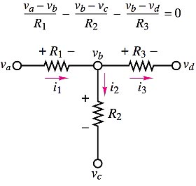
Ques.74. What is the total anode current of SCR in the equivalent circuit from the two transistors (T1 & T2) analogy of SCR?
- The sum of both base current
- The sum of both collector current✓
- The sum of the base current of T2 & collector current of T1
- The sum of the base current of T1 & collector current of T2
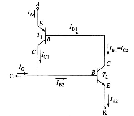
SCR is a unidirectional device and like a diode, it allows current to flow in one direction only. It can be used as a switch. The switching of SCR is controlled by the additional input called gate and biasing conditions. It can be used as a rectifier to convert AC signals to DC signals. Construction The SCR is a four-layer p-n-p-n device, where p and n layers are alternately arranged. The outer layers are heavily doped. There are three p-n junctions called J1, J2, and J3. The outer P-layer is called anode and outer n-layer is called cathode, middle P-layer is called the gate. The terminals are taken out from their layers. Anode must be positive with respect to the cathode so that SCR will be forward biased. To turn on an SCR, a current is to be passed through the gate terminal. Hence it is a current operated device. Two Transistor Model of SCR The operation of an SCR can also be explained in a very simple way by considering it in terms of two transistors. This is known as the two transistor analogy of the SCR. The SCR can be considered as an NPN and a PNP transistor, where the collector of one transistor is attached to the base of the other and vice versa. This model is obtained by splitting the two middle layers of the SCR into two separate parts. In the above figure, two middle layers of the SCR is split into two separate parts i.e PNP transistor T1 and NPN transistor T2. Collector current in the NPN transistor acts as the base current for the PNP, and analogously, the collector current of the PNP acts as base current driving the NPN transistor. The sum of two collector currents is equal to the external circuit current Ia, entering at anode terminal A. ∴ Ia = IC1 + IC2 The relation between the anode current and the current gain of transistor t1 and t2 is given as Ia = (α2Ig) ⁄ [1 − (α1 + α2) Where Ia = Anode current Ig = Gate current α1 = Current gain of transistor t1 α2 = Current gain of transistor t2 From the above, equation if, (α1 + α2) = 1, then anode current becomes infinite, i.e. it suddenly attains very high value approaching infinity. The device latches into conduction (ON) state from nonconducting (OFF) state. This action of SCR is called the regenerative action. As the gate current IG is of such a value that (α1 + α2) approaches unity, the SCR gets turned on.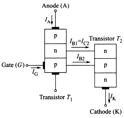
Ques.75. What is the total resistance of a series circuit and parallel circuit respectively for resistor R1 = 2 Ohms, R2 = 4 ohms R3 = 1ohms?
- 1.75, 7
- 7, 1.5
- 7, 0.57✓
- 7, 7
When the resistance is connected in parallel the total resistance will be 1/R = 1/R1 + 1/R2 + 1/R3 1/R = 1/2 + 1/4 + 1 1/R = (2 + 1 + 4)/4 R = 0.57 When the resistance is connected in series total resistance will be R = 2 + 4 + 1 = 7
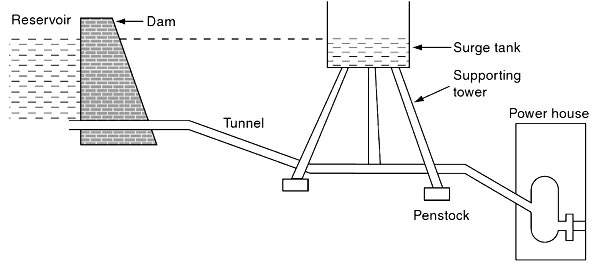
Ques.76. Why surge tanks are used in a hydroelectric power system?
- For the protection of Penstock✓
- For the protection of spillways
- For the protection of turbines
- None of these
The power output of a generator at a particular hydroelectric power plant is directly proportional to the discharge, i.e., P ∝ Q and the load on the system varies so that the load on the generator goes on fluctuation. This requires that the water intake to the turbine be regulated accordingly. Thus, when the load on the alternator is reduced, the governor closes the turbine gates. This sudden closure of the turbine gates causes an increase in the pressure in the penstock. This is referred to as water hammer. Similarly, an increased load on the alternator causes the governor to open the turbine gates to allow more water. This sudden opening of the turbine gates has a tendency to cause a vacuum in the penstock. Both the water hammer and the negative pressure (vacuum) are detrimental to the proper functioning of the penstocks and are to be avoided. A surge tank is used to take care of these sudden changes in the water requirements and the consequent water hammer of vacuum. In the figure, a surge tank is shown. It acts as a relief valve by allowing a sufficient quantity of water to flow into or out of the surge tank. A reduction in load demand allows water to flow into the surge tank, thereby raising the water level. So, a retarding head is created and the velocity of water in the penstock is decreased. Similarly, an increased demand causes the water to flow out of the surge tank. This reduces the water level in the surge tank.Surge tank
Ques.77. For an SCR, the gate-cathode characteristics have a slope of 130. The gate power dissipation is 0.5 watt. Find Ig.
- 6.2 mA
- 0.62 A
- 620 mA
- 62 mA✓
Given Power P = Vg.Ig = 0.5 Slope Vg/Ig = 130 = Vg = 130.Ig ∴ 130.Ig2 = 0.5 Ig = 62 mA
Ques.78. Candela is the unit of
- Luminous flux
- Luminous intensity✓
- Wavelength
- Frequency
Ques.79. The average power consumed in the purely Inductive circuit is:-
- 0.25
- 0✓
- 0.5
- 1
In the purely inductive circuit the current lag behind the voltage by 90°. Let us see what really takes place in a purely inductive circuit. During one-quarter cycle of an alternating source of e.m.f., energy is stored in the magnetic field of the inductor. This energy is supplied by the source. During (the next quarter cycle, tile stored energy is returned to the source. For this reason, average power absorbed by a pure inductor over a complete cycle is zero.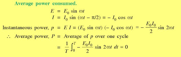
Ques.80. Polyethylene, Nylon, Teflon, PET, and vinyl are all example of
- Thermoplastics✓
- None of these
- Titanium alloys
- Elastomer
Thermoplastic:- A thermoplastic, or thermo-softening plastic, is a plastic material, a polymer, that becomes pliable or moldable above a specific temperature and solidifies upon cooling. Thermoplastics can be reheated repeatedly without undergoing any chemical change. This allows them to be reshaped or recycled into new materials. Examples are PVC, Nylon polyethylene and polypropylene. Elastomers:- These are polymers that have good elasticity, i.e. they can be distorted under pressure but will return to their original shape when the pressure is removed. Natural rubber, Silicone rubbers, neoprene rubber, Nitrile rubbers, buna-s, and buna-n are all examples of such elastomers.

