
The VI characteristics of UJT is Similar to
Right Answer is:
Tunnel diode in some respects
SOLUTION
Unipolar Junction Transistor (UJT)
The VI characteristics of UJT is Similar to Tunnel diode in some respects.
A UJT is a three-terminal semiconductor switching device. This device has a unique characteristic that when it is triggered, the emitter current increases regeneratively until it is limited by the emitter power supply. Due to this characteristic, the UJT can be employed in a variety of applications e.g., switching, pulse generator, sawtooth generator, etc.
Construction: The figure shows the structure of a unijunction transistor. It consists of an n-type silicon bar with an electrical connection on each end. The leads to these connections are called base leads base. One B1 and base two B2. Partway along the bar between the two bases, nearer to B2 than B1, a p-n junction is formed between a p-type emitter and the bar. The lead to this junction is called the emitter lead E.
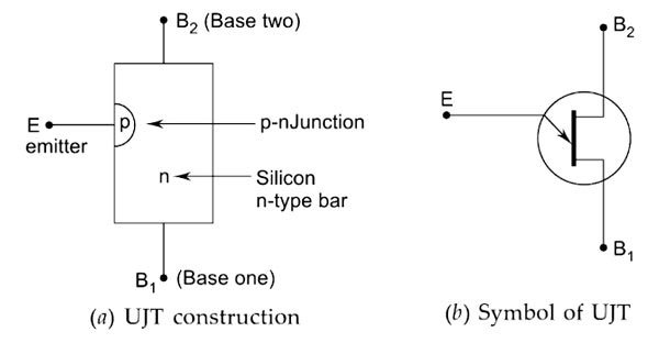
- Since the device has one p-n junction and three leads, it is commonly called UJT.
- With only one p-n junction, a device is really a form of diode because of the two bases taken from one section of the diode, the device is also called a double-based diode.
- The emitter is heavily doped having many holes. The n-region is lightly doped.
Characteristics of UJT
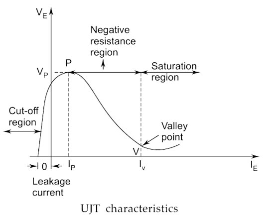
- The figure shows the curve between emitter voltage (VE) and emitter current (IE) Of a UJT at a given voltage VBB between the bases. These is known as the emitter characteristics of UJT.
- Initially, in the cut-off region, as VE increases from zero, slight leakage current flows from terminal B2 to the emitter. This current is due to minority carriers in the reverse-biased diode.
- Above a certain value of VE, forward IE begins to flow, increasing until the peak voltage Vp and current Ip are reached at point P.
- After the peak point P. an attempt to increase VE is followed by a sudden increase in emitter current IE with a corresponding decrease in VE. This is a negative resistance portion of the curve because of an increase in IE. VE decreases. The device, therefore, has a negative resistance region that is stable enough to be used with a great deal of reliability in many areas, e.g., trigger circuits, sawtooth generators, biasing circuits.
- The negative portion of the curve lasts until valley point V is reached with valley point voltage Vv and valley-point current Iv. After the valley point, the device is driven to saturation.