A. Current series positive feedback amplifier
B. Voltage series negative feedback amplifier
C. Current series negative feedback amplifier
D. Voltage series positive feedback amplifier
Answer: C
Voltage to current converter is also called a current series negative feedback amplifier because the feedback voltage across the internal resistor applied to the inverting terminal depends on the output current and is in series with the input difference voltage.
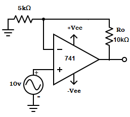
2. Given voltage to current converter with the floating load. Determine the output current?
A. 3mA
B. 6mA
C. 4mA
D. 2mA
Answer: D
Output current, Io = Vin /R1 = 10/5kΩ =2mA.
3. Which of the following application uses voltage for the current converter?
A. Low voltage dc and ac voltmeter
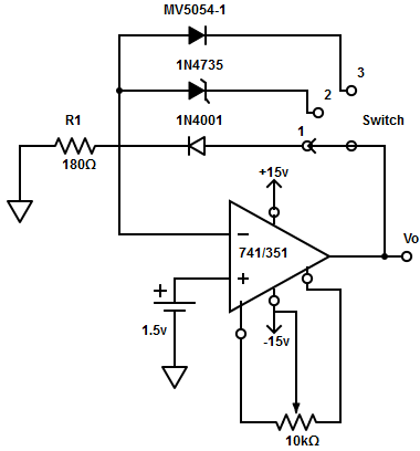
B. Diode match finding
C. Light-emitting diode
D. All of the mentioned
Answer: D
In all the applications mentioned above, the input voltage Vin is converted into an output current of Vin/R1, or the input voltage appears across the resistor.
4. The op-amp in low voltage DC voltmeter cannot be nullified due to
A. D’Arsonaval meter movement
B. Offset voltage compensating network
C. Selection of switch
D. Gain of amplifier
Answer: A
The op-amp sometimes cannot be nullified because the output is very sensitive to even slight variation in wiper position of D’Arsonaval meter movement (ammeter with a full-scale deflection of 1mA.
5. What is the maximum input voltage that has to be selected to calibrate a dc voltmeter with a full-scale voltage range of 1-13v.
A. ≤ ±14v
B. ≥ ±13v
C. ≤ ±15v
D. = ±14v
Answer: A
The maximum input voltage has to be ≤ ±14v, to obtain the maximum full-scale input voltage of 13v.
6. Higher input voltage can be measured in low voltage DC voltmeter using
A. Smaller resistance value
B. Higher resistance value
C. Random resistance value
D. All of the mentioned
Answer: B
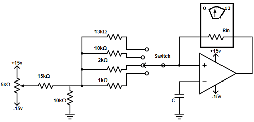
Higher resistance values are required to measure relatively higher input voltage. For example, if the range of switch is at x10 position in the low voltage dc voltmeter then, the corresponding resistance value would be 10kΩ. So, it requires a 10v input to get a full-scale deflection (if 1v causes a full-scale deflection in the ammeter with a full-scale deflection of 1mA.
7. In the diagram given below, determine the deflection of the ammeter with a full-scale deflection of 1mA when the switch is at X2kΩ. Consider resistance of the offset voltage compensating network to be 10Ω.
A. Full-scale deflection in the ammeter
B. Half scale deflection in the ammeter
C. Quarter scale deflection in the ammeter
D. No deflection occurs in the ammeter
Answer: B
Given
Vin=1v
R1=10+2kΩ ≅2kΩ
Io = Vin/R1= 1v/2kΩ =0.5mA.
This means that 2v causes half-scale deflection of the ammeter.
8. How to modify a low voltage DC voltmeter to a low voltage ac voltmeter
A. Add a full-wave rectifier in the feedback loop
B. Add a half-wave rectifier in the feedback loop
B. Add a square wave rectifier in the feedback loop
B. Add a sine wave rectifier in the feedback loop
Answer: A
A combination of an ammeter and a full-wave rectifier can be employed in the feedback loop to form an ac voltmeter.
9. Determine the full-scale range for the input voltage if the resistance in series with meters is 1kΩ, 2kΩ, 47kΩ, and full-scale meter movement is 1mA in a low voltage AC voltmeter?
A. 1.0 to 7.48 Vrms
B. 1.1 to 7.48 Vrms
C. 1.2 to 7.48 Vrms
D. 1.3 to 7.48 Vrms
Answer: B
The minimum and maximum values of resistors are 1kΩ and 6.8kΩ. So, the range for the input voltages are