1. Loading effect is caused due to ______ of the voltmeter.
Low Capacitance
High Inductance
Low Sensitivity
High Sensitivity
Answer.3. Low Sensitivity
Explanation:
The loading effect is caused due to low sensitivity of the voltmeter. When we make voltage measurements in high-resistance circuits, we should use a high sensitivity voltmeter to prevent the loading effect of the voltmeter. The effect is less noticeable in low-resistance circuits because the loading effect is less.
2. To minimize the loading effect of the circuit under test, the input impedance of the device must:
Be very high
Be capacitive
Be very low
Match with the input impedance of the circuit
Answer.1. Be very high
Explanation:
When a voltmeter having an internal resistance of Rm is connected in parallel with a load resistance RL of the circuit under test, the circuit conditions will be altered.
The effective resistance will be the parallel combination of RL and Rm. The voltmeter indicates the voltage across this effective resistance, where the indicated voltage will always be less than the true voltage. This is known as the loading effect.
Hence the instrument must possess high input impedance to reduce the loading effect.
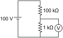
3. If the voltmeter has a range of 2 V and sensitivity is 1 kΩ/V, what will be the reading of the voltmeter in the circuit?
0.33 V
0.66 V
0.99 V
0.44 V
Answer.2. 0.66 V
Explanation:
Given: Vfsd = 2 V, Sensitivity (s) = 1 kΩ /V
We know that,
Rm = Vfsd × S
Rm = 2 × 1 kΩ /V = 2 kΩ
This 2kΩ in parallel with the 1kΩ,
so parallel equivalent resistance is,
Rparallel = (2 × 1)/3 = 0.666 kΩ
Now this resistance in series with 100kΩ,
By using the voltage division rule, we can find out the voltage across the voltmeter.
So, Voltage across the voltmeter
V2 = (R2 × V)/(R1 + R2)
V2 = (.66 × 100)(100 + 0.66)
V2 = 0.66 V
4. A voltmeter has a sensitivity of 2000 Ω/V reads 100V on its 150 scales when connected across an unknown resistor in series with a multi-ammeter. When the milli-ammeter reads 5 mA, The magnitude of the error (in %) due to the loading effect of the voltmeter is.
7%
10%
5%
3%
Answer.1. 7%
Explanation:
Sensitivity = 2000 Ω/v
Full scale deflection = 150 Ω
Resistance of voltmeter = 2000 × 150
(Rv) = 300 kΩ
Total circuit resistance
(RT) = 100/(5 × 10−3) = 20 kΩ
Let the unknown resistance is Rx
As the voltmeter is in parallel wit the unknown resistance we have
RT = (RxRv)/(Rx + Rv)
Rx = (RTRv)/(Rv − RT)
Rx = (200 × 300)(300 − 20) = 21.42 kΩ
Error = (Measured Value − True Value)/True Value
= 20 − 21.42/21.42
= -6.669
magnitude of the percentage error = 6.669%
5. Which one of the following meters has a maximum loading effect on the circuit under measurement?
1000 Ω/volt
100 Ω/volt
1 MΩ/volt
10 MΩ/volt
Answer.2. 100 Ω/volt
Explanation:
Sensitivity is also called a Figure of merit or Scale Factor.
It indicates the relation between change in output readings for change in input reading for an instrument.
This relation may be linear or nonlinear.
Sensitivity S = Change in output/Change in Input
In the given meters,
100 Ω/volt has the least sensitivity
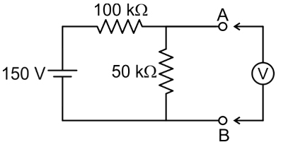
6. For the network shown in the figure the voltage across terminal AB has measured a voltmeter of sensitivity 1kΩ/V, then find the percentage error in the measurement.
7. A voltmeter has a sensitivity of 500 Ω/V reads 75 V on its 100 V scale when connected across an unknown resistor in series with a multi-ammeter. When the ammeter reads 2.5 mA, the error (in %) due to the loading effect of the voltmeter is
60%
−60%
50%
−50%
Answer.2. −60%
Explanation:
Total Circuit resistance
(Rm) = Vr/Ar = 75/2.5 = 30kΩ
, Vr and Ir is reading of voltmeter & ammeter.
Resistance of voltmeter, Rv = 100 × 500 = 50 kΩ
As the voltmeter is in parallel with the unknown resistance, we have,
Rm = (RxRv)/(Rx + Rv)
RT = (RmRv)/(Rv − Rm)
RT = (50 × 30)(50 − 30) = 75 kΩ
Error = (Measured Value − True Value)/True Value
= 30 − 75/75
the magnitude of the percentage error = -60%
8. The ammeter loading effect is due to the ______ of the ammeter.
High Resistance
Low Resistance
No loading Effect In ammeter
High Impedance
Answer.3. No loading Effect In ammeter
Explanation:
Ideally, the ammeter has zero resistance and practically it has very low resistance. There will be no loading effect due to the ammeter, but a small amount of voltage drop occurs due to the internal resistance.
9. Statement (I): The ammeter loading effect is due to the high resistance of the ammeter.
Statement (II): Increasing the resistance of the voltmeter will reduce the voltmeter loading effect.
Both statement (I) and Statement (II) are individually true and Statement (II) is the correct explanation of Statement (I)
Both statement (I) and Statement (II) are individually true and Statement (II) is not the correct explanation of Statement (I)
Statement (I) is true but Statement (II) is false
Statement (I) is false but Statement (II) is true
Answer.4. Statement (I) is false but Statement (II) is true
Explanation:
When a voltmeter having an internal resistance of Rm is connected in parallel with load resistance RL of a circuit under test, the circuit conditions will be altered.
The effective resistance will be the parallel combination of RL and Rm.
The voltmeter indicates the voltage across this effective resistance, where the indicated voltage will always be less than the true voltage. This is known as the loading effect.
If the sensitivity of the instrument is high i.e. with the high resistance, the loading effect will be less.
Ammeter:
Ideally, the ammeter has zero resistance and practically it has very low resistance. There will be no loading effect due to the ammeter, but a small amount of voltage drop occurs due to the internal resistance.
Therefore, Statement (I) is false but Statement (II) is true.
10. The loading effect of voltmeter is reduced using:
Low internal resistance
Medium internal resistance
High internal resistance
None of these
Answer.3. High internal resistance
Explanation:
When selecting a meter for a particular measurement, the sensitivity rating is very important. A low sensitive meter may give an accurate reading in a low resistance circuit but will produce totally inaccurate reading in high resistance circuit.
The voltmeter is always connected across the two points between which the potential difference is to be measured.
If it is connected across a low resistance then as voltmeter resistance is high, most of the current will pass through a low resistance and will produce the voltage drop which will be nothing but the true reading.
But if the voltmeter is connected across the high resistance then due to two high resistances in parallel, the current will divide almost equally through the two paths. Thus the meter will record the voltage drop across the high resistance which will be much lower than the true reading.
When the voltmeter resistance is not high enough, connecting it across a circuit can reduce the measured voltage, compared with the voltage present without the voltmeter.