21. What is the reading (in kW) of both the wattmeter, when measuring the power of a three-phase three-wire system having an input of 5 kW and power factor of 0.866?
5, 0
3.33, 1.67
2.5, 2.5
1, 4
Answer.2. 3.33, 1.67
Explanation:
In two wattmeter method, the power factor is given by
The wattmeter W2 reads positive (i.e.upscale) because for the given conditions (i.e. ( 90° > φ > 60°), the phase angle between voltage and current will be less than 90°. However, in wattmeter W1, the phase angle between voltage and current shall be more than 90° and hence the wattmeter gives a negative (i.e. downscale) reading.
Wattmeter cannot show negative reading as it has only a positive scale. An indication of negative reading is that the pointer tries to deflect in a negative direction i.e. to the left of zero.
In such a case, reading can be converted to positive by interchanging either pressure coil connections or by interchanging current coil connections. Remember that interchanging connections of both the coils will have no effect on wattmeter reading.
(iv) When P.F reads zero (φ = 90°)
Such a case occurs when the load consists of pure inductance or pure capacitance
In this condition, the two wattmeter reads equal and opposite i.e W1 + W2 = 0
23. In the measurement of the power of balanced load by two wattmeter method in a 3-phase circuit, The readings of the wattmeters are 4 kW and 2 kW respectively, the latter is being taken after reversing the connections of the current coil. the power factor and reactive power of the load is
0.2 & 6 kVAR
0.2 & 6 √3 kVAR
0.32 & 2 kVAR
0.32 & 2 √3 kVAR
Answer.2. 0.2 & 6 √3 kVAR
Explanation:
Given that,
Reversing the connections
W1 = 4 kW, W2 = – 2 kW
Total reactive power (Q) = √3[4 – (- 2)] = 6 √3 kVAR
24. Which of the following is not a method of resistance measurement?
Ammeter-voltmeter method
Post-office box method
Ohm-meter method
Two wattmeter method
Answer.2. Two wattmeter method
Explanation:
The instrument most commonly used for active power measurement is the wattmeter.
It is essentially an inherent combination of an ammeter and a voltmeter and, therefore, consists of two coils known as the current coil and pressure coil.
The current coil is inserted in series with the line carrying the current to be measured and the pressure coil in series with a high non-inductive resistance connected across the load or supply terminals.
The wattmeter method is not used for resistance Measurement.
25. What is the angle between (in degrees) the planes of two moving coils of a dynamometer type 3-phase power factor meter?
0
60
90
120
Answer.4. 120
Explanation:
Dynamometer type 3-phase power factor meter:
The power factor meter circuit includes two fixed coils namely the pressure coil and a current coil.
The pressure coil is connected across the circuit while the current coil is connected such that it can carry a circuit current or a definite fraction of current.
The power factor meter circuit includes two moving coils. These are rigidly connected to each other so that their axes are at 120° to each other.
These coils move together and carry the pointer which indicates the power factor of the circuit.
Unlike, the single-phase dynamometer type power factor meter, it has both voltage coils in series with pure resistances. Instead of fixing the voltage coils 90° apart, we fix those coils 120° apart.
26. Three wattmeter method of power measurement can be used to measure power in
Both balanced and unbalanced circuits
Balanced circuits
None of the options
Unbalanced circuits
Answer.1. Both balanced and unbalanced circuits
Explanation:
A 3-wattmeter method is used to measure power in 3 phases using a 4 wire system which is based on Blondel’s theorem.
The three-wattmeter method of power measurement will work regardless of whether the load is balanced or unbalanced, wye-or delta-connected.
The three-wattmeter method is well suited for power measurement in a three-phase system where the power factor is constantly changing. The total average power is the algebraic sum of the three wattmeter readings.
27. In the wattmeter if the impedance is 5∠36.87° and the supply from the current transformer is 5/50A. The voltage across the pressure coil is 200 ∠0° V. Then the average power is
640 W
320 W
800 W
400 W
Answer.1. 640 W
Explanation:
Given,
Vpc = V = 200 ∠0° V
Z = Impedance = 4 +j3 = 5∠36.87°
I= Current from supply = V/Z = 200∠0°/5∠36.87° = 40∠-36.87°A
Icc = 40 × (5/50) = 4 A
ϕ = 36.87°
Average power = 200 × 4 × cos 36.87° = 640 W
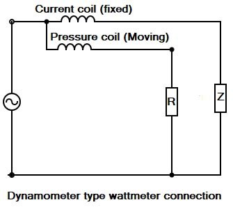
28. The moving coil in a dynamometer wattmeter is connected
In series with the fixed coil
Across the supply
In series with the load
Any one of the above
Answer.1. In series with the fixed coil
Explanation:
When a dynamometer instrument is used as a wattmeter, the fixed coils are connected in series with the load and carry the load current while the moving coil is connected across the load through a series multiplier R and carries a current proportional to the load voltage.
The fixed coil (or coils) is called the current coil and the movable coil is known as the potential coil.
29. In the two-wattmeter method, the readings of the two wattmeters are 500 W, 500 W respectively. The load power factor in a balanced 3-phase 3-wire circuit is:
The power measured by the dynamometer wattmeter at any instant is the instantaneous power absorbed by the three loads connected in three phases. In fact, this power is the average power drawn by the load since the Wattmeter reads the average power because of the inertia of their moving system.
The power measured by each wattmeter varies from instant to instant. Due to the inertia of the moving system, the wattmeter measures the average power. The sum of the two wattmeter readings gives the total 3-phase power.