32. Two meters X and Y required 40 mA and 50 mA respectively for full-scale deflection. Then
Both are equally sensitive
Data are insufficient to comment
X is more sensitive than Y
Y is more sensitive than X
Answer.3. X is more sensitive than Y
Explanation:
The sensitivity of the instrument is Inversely proportional to current
Where
Sensitivity ∝ 1/Im
Where Im is the current
∴X is more sensitive than Y
33. In the case of the two-wattmeter method for measuring the power of a balanced 3ϕ load, the whole power is measured by one of the two wattmeters when:
The power factor is unity
The power factor is more than 0.5 but less than 1
The power factor is 0.5
The power factor is less than 0.5 but more than 0
Answer.3. The power factor is 0.5
Explanation:
The reading of two wattmeters can be expressed as
W1 = VLILcos(30 + φ) W2 = VLILcos(30 − φ)
(i) When PF is unity ( φ = 0°)
W1 = VLILcos30° W2 = VLILcos30°
Both wattmeters read equal and positive reading i.e upscale reading
(ii) When PF is 0.5 (φ = 60°)
W1 = VLILcos90° = 0 W2 = VLILcos30°
Hence total power is measured by wattmeter W2 alone
34. In the measurement of power in a balanced 3-phase circuit by two wattmeter method if the two-wattmeters show equal readings. Then the power factor of the circuit is
Zero
Unity
0.8 lagging
0.8 leading
Answer.2. Unity
Explanation:
The reading of two wattmeters can be expressed as
W1 = VLILcos(30 + φ) W2 = VLILcos(30 − φ)
(i) When PF is unity ( φ = 0°)
W1 = VLILcos30° W2 = VLILcos30°
Both wattmeters read equal and positive reading i.e upscale reading
(ii) When PF is 0.5 (φ = 60°)
W1 = VLILcos90° = 0 W2 = VLILcos30°
Hence total power is measured by wattmeter W2 alone
(iii) When PF is less than 0.5 but greater than 0 i.e ( 90° > φ > 60°)
The wattmeter W2 reads positive (i.e.upscale) because for the given conditions (i.e. ( 90° > φ > 60°), the phase angle between voltage and current will be less than 90°. However, in wattmeter W1, the phase angle between voltage and current shall be more than 90° and hence the wattmeter gives negative (i.e. downscale) reading.
Wattmeter cannot show negative reading as it has only a positive scale. An indication of negative reading is that the pointer tries to deflect in a negative direction i.e. to the left of zero. In such a case, reading can be converted to positive by interchanging either pressure coil connections or by interchanging current coil connections. Remember that interchanging connections of both the coils will have no effect on wattmeter reading.
(iv) When P.F reads zero (φ = 90°)
Such a case occurs when the load consists of pure inductance or pure capacitance
In this condition, the two wattmeter reads equal and opposite i.e W1 + W2 = 0
35. The minimum number of wattmeter(s) required to measure 3-phase, 3-wire balanced or unbalanced power is
1
2
3
4
Answer.2. 2
Explanation:
According to Blondell’s theorem, the no. of watt meters to be required to measure the total power in n-phase system is either N (or) N–1.
When a separate neutral wire is available in the system the no. of watt meters to be required is N.
When the neutral wire is not available in the system, then the no. of watt meters to be required is (N–1).
Power is measured according to Blondel’s theorem
Phase/conductor
Wattmeter required
n
n-1
n with neutral wire
n
One line is acting as a common line for the return path. Hence the minimum number of wattmeters required is 2.
37. A wattmeter is marked 15A/30A, 300V/600V, and its scale is marked up to 4500 watts. When the meter is connected for 30A, 600V, the point indicated 2000 watts. The actual power in the circuit is
2000 watts
4000 watts
6000 watts
8000 watts
Answer.4. 8000 watts
Explanation:
Power consumed by wattmeter = CT ratio × PT ratio × VIcosΦ……..1
In the above question
Power consumed by wattmeter = 2000 watts
CT ratio = 15 / 30
PT ratio = 300 / 600
VI = 600 × 30
Putting all the value in equation number 1 we get
2000=(15/30) × (300/600) × 600 × 30 × cosΦ
CosΦ = 0.4444
Power = VI cosΦ = 600 x 30 x 0.4444
Power = 7999.2 ≅ 8000 watts
38. Measurement of power factor for balanced load by two wattmeters for lagging power factor is:
39. The power in an unbalance 3-phases 4-wire circuit can be measured by using a _______ method.
4 Wattmeter
3 wattmeter
2 wattmeter
1 wattmeter
Answer.2. 3 wattmeter
Explanation:
A 3-wattmeter method is used to measure power in 3 phases using a 4-wire system which is based on Blondel’s theorem.
The three-wattmeter method of power measurement will work regardless of whether the load is balanced or unbalanced, wye-or delta-connected. The three-wattmeter method is well suited for power measurement in a three-phase system where the power factor is constantly changing. The total average power is the algebraic sum of the three wattmeter readings.
40. In two wattmeter method of measuring 3 phase power, the power factor is 0.5, then one of the wattmeters will read
W/2
0
0.577 W
1.414 W
Answer.2. 0
Explanation:
The reading of two wattmeters can be expressed as
W1 = VLILcos(30 + φ) W2 = VLILcos(30 − φ)
(i) When PF is unity ( φ = 0°)
W1 = VLILcos30° W2 = VLILcos30°
Both wattmeters read equal and positive reading i.e upscale reading
(ii) When PF is 0.5 (φ = 60°)
W1 = VLILcos90° = 0 W2 = VLILcos30°
Hence total power is measured by wattmeter W2 alone
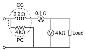
41. While measuring power observed by the load using the arrangement shown in the figure, the obtained values voltmeter and ammeter readings are 150 V and 12 A respectively. If the load power factor is unity, the wattmeter reading will be
1800 W
1756.8 W
1824.2 W
1843.2 W
Answer.4. 1843.2 W
Explanation:
Current through current coil (I) = ammeter reading = 12 A.
Power factor = cos ϕ = 1
Resistance of current coil = Rcc = 0.2 Ω
Ammeter resistance = RA = 0.1 Ω
The pressure coil voltage = The voltage drop across the current coil and ammeter + voltmeter reading.