For a thyristor shown is
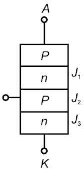
Right Answer is:
J1, J2 are forward biased and j3 reversed biased
SOLUTION
SCRs have three operating regions such as
- Forward conduction state
- Forward blocking state
- Reverse blocking state
Forward Blocking Region
The forward blocking region is the widest operating region. In this region, the anode terminal is positive with respect to the cathode. Junctions J1and J3 are forward biased (FB), but junction J2 is reverse biased (RB). The anode current (IA) and the voltage across anode to cathode (VAK) vary in a wide range with the amplitude of gate current.
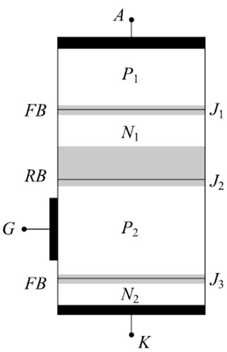
The width of the forward-biased junction depletion layer (J1 and J3) and the reverse-biased junction depletion layer (J2) depend on the dropping density and biasing voltage. The forward-biased junction depletion layer width is thin while the reverse-biased junction depletion layer width is thick. When a voltage is applied, as junction J1and J3 are forward biased, the applied voltage should appear across junction J2 as depicted in Fig.
Forward Conduction Region
When the SCR is forward biased and the gate current is applied through the gate terminal (G), the junction J2 breakdown. Then all the layers are filled with charge carriers. The SCR provides a very low impedance between A and K and current flows through anode-to-cathode and amplitude of the current is limited by external circuit parameters. The value of gate voltage VG varies within a few volts.
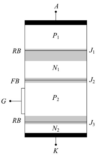
Reverse Blocking Region
During reverse biased, the anode terminal is negative with respect to the cathode, junctions J1 and J3 are reverse biased and junction J2 is forward biased as depicted in Fig. As the N1 layer is lightly doped and the wide reverse-biased depletion layer at J2 is large. The depletion layer width of junctions J2 and J3 are thin. A reverse leakage current flows from the cathode (K) to anode (A). When the applied voltage increases to breakdown voltage VBD, the junction breaks.