1. For a voltage source to be neglected, the terminals across the source are ______
Replaced by inductor
Short circuited
Replaced by some resistance
Open circuited
Answer.2. Short Circuited
Explanation
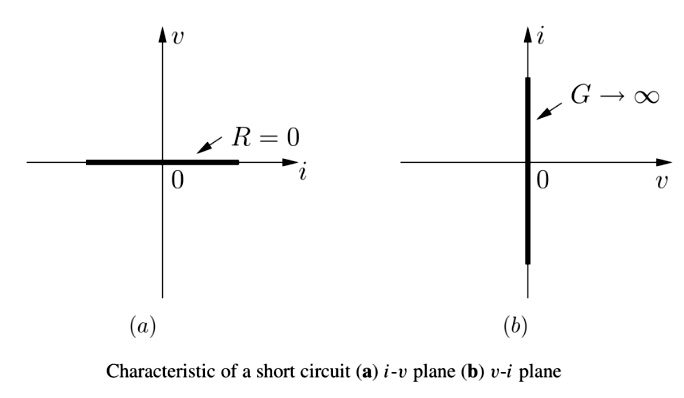
If we put R=0, then v(t) =0 whatever be the current through the element. In this case, the 2-terminal resistor is said to be a short circuit. In the v-i plane, a short-circuit characteristic is the i axis as shown in Fig. is zero, that is, R=0 and equivalently G = ∞,
or
A two-terminal resistor is called a short circuit iff its voltage v is identically zero irrespective of the currenti;i.e., f(v,i) = v =0.
In a short circuit, there’s zero voltage across a wire, no matter how much current flows through it. Because there’s no voltage across a short circuit, there’s zero absorbed power (p = 0 watts).
When you connect two points in a circuit that have different voltages, you get a short circuit. When this happens, you bypass the other parts of a circuit (called the load) and establish a path of low resistance, causing most of the current to flow around or away from some other parts in the circuit. Accidental short circuits, especially between the high and low voltages of a power supply, can cause strong current to flow, possibly damaging or overheating the power supply and the circuit if the circuit isn’t protected by a fuse.
2. To neglect a current source, the terminals across the source are
Open-circuited
Short-circuited
Replaced by an inductor
Replaced by some resistance
Answer.1. Open-circuited
Explanation:-
(Open Circuit):- A two-terminal resistor is called an open circuit if its current i is identically zero irrespective of the voltage v; i.e., f(v,i) =i =0. The characteristic of an open circuit is the v axis in the v—i plane, with zero slopes (G = 0). In the i-v plane, it has an infinite slope, R — ∞, as shown in fig.
An open circuit occurs when there’s no current flow for any applied voltage, like when you blow a fuse. Because there’s no current flow, there’s no power absorbed (p = 0 watts) in an open-circuit device.
3. In the case of ideal current sources, they have _______
Zero internal resistance
The low value of voltage
A large value of current
Infinite internal resistance
Answer.4. Infinite internal resistance
Explanation:-
An ideal current source (also called constant current source) is one that will supply the same current to any resistance connected across its terminals. The ideal current source has infinite resistance.
The internal resistance is the ratio of change of voltage across the device to the change in current through it, we see that the internal resistance must be infinitely large. The voltage across the source changes but the current, in an ideal source, does not. Hence the change in the current is zero, and any number, when divided by zero, gives an infinitely large quotient.
4. A dependent source _______
Is always a voltage source
Maybe a current source or a voltage source
Is always a current source
None of the mentioned
Answer.2. Maybe a current source or a voltage source
Explanation:-
The category of a source whose output (current or voltage) is a function of some other voltage or current in a circuit is known as a dependent source. A different symbol, in the shape of a diamond, is used to represent the dependent source and distinguish it from the independent source.
Voltage and current sources can be either independent or dependent. A dependent source is controlled by an independent source, and a source can either be of a DC source or of a time-dependent (e.g. AC) type.
The important thing to remember about these sources is that they can either deliver or absorb electric power, generally maintaining either voltage or current. This behavior is of particular interest for circuit analysis and led to the creation of the ideal voltage source and the ideal current source as basic circuit elements.
5. A practical voltage source can also be represented as _______
Resistance in series with an ideal current source
Resistance in series with an ideal voltage source
Resistance in parallel with an ideal voltage source
None of the mentioned
Answer.2. Resistance in series with an ideal voltage source
Explanation:-
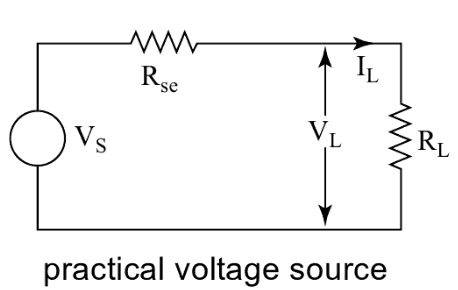
Practical voltage Sources
A practical voltage source is shown as an ideal voltage source in series with a resistance. This resistance is called the internal resistance of the source, as shown in Fig.
A practical voltage source, such as a battery, has drooping load characteristics due to some internal resistance. The terminal voltage falls as the current increases due to its internal resistance. A voltage source has small internal resistance in series.
6. A practical current source can also be represented as ________
Resistance in parallel with an ideal current source
Resistance in parallel with an ideal voltage source
Resistance in series with an ideal current source
None of the mentioned
Answer.1. Resistance in parallel with an ideal current source
Explanation:-
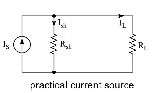
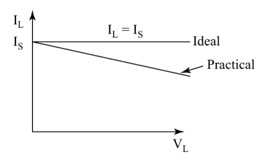
A practical current source is shown as an ideal current source in parallel with its internal resistance, as shown in Fig.
In a practical current source, the magnitude of the current falls as the voltage across its terminals increases. A current source has some high internal resistance in parallel. For an ideal current source, Rsh = ∞
7. Which of the following statement is incorrect about active and Passive elements?
The inductor is a passive element
The current source is an active element
The resistor is a passive element
The voltage source is a passive element
Answer.4. The voltage source is a passive element
Explanation:-
Active and passive components form the two main types of electronic circuit elements.
An active component supplies energy to an electric circuit and hence has the ability to electrically control the flow of charge.
A passive component can only receive energy, which it can either dissipate or absorb.
The resistor, an inductor is a passive element of an electrical circuit. While current source, voltage source, and battery are all active elements.
8. Which of the following is true about an ideal voltage source?
Zero resistance
Small emf
Large emf
Infinite resistance
Answer.1. Zero Resistance
Explanation:-
An ideal voltage source is one in which the value of the terminal voltage is constant with respect to the value of the current at any time. An ideal voltage source has zero or negligible internal resistance that there is a negligible voltage drop in the internal resistance due to change in current. Consequently, the terminal voltage remains constant.
9. The terminals across the source are _____ if a current source is to be neglected.
Replaced by a source resistance
Open circuited
Replaced by a capacitor
Short circuited
Answer.2. Open circuited
Explanation
ldeally a current source has to supply constant output current irrespective of the load. The terminals across the source are open-circuited if a current source is to be neglected.
10. The capacitor C which has zero initial charge at t = 0+ acts as a
Open circuit
Short circuit
A current source
A voltage source
Answer.4. A voltage source
Explanation
Initial conditions
T=0- represents the instant before the event. In this case, the switch has been closed for some considerable time
T=0 is the Initial condition. The switch is closed i.e, switched on.
T=0+ is the instant after the event that means the switch has just opened.
Energy cannot change instantaneously for elements that store energy. Thus, there are no discontinuities allowed in current through an inductor or voltage across a capacitor at any time—specifically, the value of the variable remains the same at t=0− and t = 0+.
At t=0− a capacitor acts as an open circuit. Thus at a steady state at t=0− we replaced capacitors by open circuits in the circuit.
At t = 0+ the capacitor voltage cannot change in going from t=0− to t = 0+, we replace the capacitors with voltage sources whose values are the voltages at t=0−.
A capacitor maintains a constant voltage, and the process is often called smoothing the current. It accomplishes this by using its storage capacity—its capacitance—to either donate or accept electrons when there is a drop or a spike in voltage.
If there is a voltage drop in a circuit, the capacitor will push electrons toward the direction of the source voltage, acting as a voltage source. This may seem counterintuitive because we are used to thinking of electrons flowing in a single direction, from the positive to the negative terminals of a power supply. But electrons also flow “backward” in a circuit if the charge in the capacitor is positive compared to the voltage entering the capacitor. Electrons are still flowing positive to negative, but until the charges match, the capacitor acts as source voltage until it has exhausted its capacitance.
11. The Inductor L which has zero initial charges at t = 0+ acts as a
Open circuit
Short circuit
A current source
A voltage source
Answer.3. A current source
Explanation
At t=0− when a circuit is at a steady state, an inductor acts as a short circuit. Thus at a steady-state at t=0− we replace all inductors with short circuits and capacitors by open circuits in the circuit.
At t = 0+ the inductor current cannot change in going from t=0− to t = 0+, we replace the inductors with current sources whose values are the currents at t=0−.
12. Constant voltage source is _______
Active and bilateral
Passive and bilateral
Active and unilateral
Passive and unilateral
Answer.3. Active and Unilateral
Explanation:-
Unilateral System:- If the magnitude of current flowing through a circuit element is affected when the polarity of the applied voltage is changed, the element is termed unilateral element. Such as diode, Voltage source etc.
Active Element:- An element that is a source of an electrical signal or which is capable of increasing the level of signal energy is termed an active element. Such as voltage source, current source, etc.
Hence Constant voltage source is a Unilateral and Active element
13. When the output voltage of a voltage source decreases as the load current increases are called as
Unloading of sources
Loading of sources
Deterioration of sources
Enhancement of sources
Answer.4. Enhancement of sources
Explanation:-
Loading of sources:- It has been mentioned that the output voltage of a voltage source decreases as the load current increases. If the source is loaded in such a way that the output (or load) voltage falls below a specified full load value, then the source is said to be loaded and the situation is known as loading of the source.
14. In a network consisting of linear resistors and ideal voltage source, if the value of resistors are doubled, then the voltage across each resistor _______
Increases four times
Remains unchanged
Doubled
Halved
Answer.2. Remain unchanged
Explanation:-
An ideal voltage source has the following characteristics:
(i) It is a voltage generator whose output voltage remains absolutely constant whatever be the value of the output current.
(ii) An ideal voltage source is one in which the load voltage does not change when the load resistance varies.
(iii) It has zero internal resistance so that the voltage drop in the source is zero.
(iv) The power drawn by the source is zero.
15. When a voltage source is converted into a current source or a current source into a voltage source is called as?
Source transformation
Voltage Transformation
Current Transformation
Circuit transformation
Answer.1. Source transformation
Explanation:-
Source Transformation:- A voltage source can be represented as a current source. Similarly, a current source can be represented as a voltage source.
A source transformation allows us to replace a voltage source and series resistor with a current source and parallel resistor. Doing so does not change the element current or voltage of any other element of the circuit.
16. Which of the following transformation is shown below in the given figure?
Source transformation
Voltage transformation
Current transformation
None of the above
Answer.3. Current transformation
Explanation:-
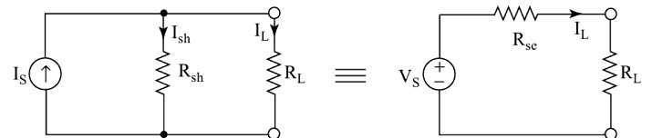
A practical current source having an ideal current Is in parallel with an internal resistance Rsh can be replaced by a voltage source Vs = I × Rsh in series with an internal resistance as shown in Fig.
A voltage source is equivalent to a current source and vice-versa, if they produce equal values of IL, and VL, when connected to the load RL, They should also provide the same open-circuit voltage and short-circuit current.
If the current source is converted into a voltage source, as in Fig.. we consider the open-circuit voltage equivalence, then
VS = I.Rsh
17. If the voltage source is converted into the current source, we consider the _________ equivalence, then:
Short circuit current
Open circuit current
Open-short circuit current
Any of the above
Answer.1. Short circuit current
Explanation:-
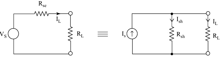
Any practical voltage source having an ideal voltage Vs, and internal series resistance Rse, can be replaced by a current source Is = Vs/Rse in parallel with an internal resistance Rsh, as shown in Fig.
If the voltage source is converted into the current source, as we consider the short-circuit current equivalence
Is = Vs/Rsh
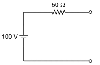
18. A voltage source having an open-circuit voltage of 100 V and internal resistance of 50 ohms is equivalent to a current source of:
2 A in parallel with 100 ohms
2 A in series with 50 ohms
0.5 A in parallel with 50 ohms
2 A in parallel with 50 ohms
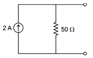
Answer.4. 2 A in parallel with 50 ohms
Explanation:-
A voltage source having an open-circuit voltage of 100 V and internal resistance of 50 ohms can be represented as a 100 V voltage source in series with a resistance of 50 ohms as shown in the below figure
The value of the current source is 100/50 = 2A and the value of the resistance remains the same.
By source transformation, we can represent this circuit as a current source with resistance in parallel.
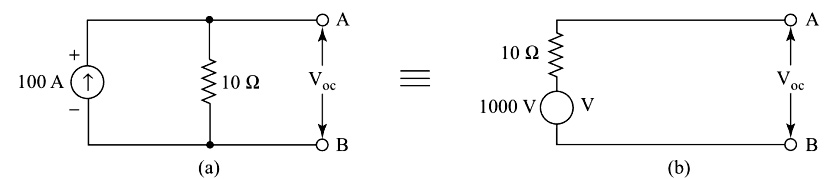
19. A current source of 100 A with an internal resistance of 10 Ω into an equivalent voltage source of
100V and 10Ω
1000V and 10Ω
10V and 10Ω
1000 V and 1000Ω
Answer.2. 1000 V and 10Ω
Explanation
Here I = 100 A, Rsh = 10 ohms
for an equivalent voltage source
V = I × Rsh
V = 100 × 10 = 1000 V
and the value of resistance will remain the same i.e 10 ohms
By source transformation, we can represent this circuit as a voltage source with resistance in series
20. Voltage source and terminal voltage can be related as ________
Terminal voltage is higher than the source emf
Terminal voltage is equal to the source emf
Terminal voltage is always lower than source emf
Terminal voltage cannot exceed source emf
Answer.3. Terminal voltage is always lower than source emf
Explanation:-
A practical voltage source like a battery has drooping load characteristics due to some internal resistance. A voltage source has small internal resistance in series while a current source has some high internal resistance in parallel. In practical voltage sources, the voltage does not
remain constant but falls slightly. Therefore the terminal voltage is always lower than source EMF.