
Definition Of an Ideal Transformer
- An ideal transformer is a perfectly coupled loose less transformer with infinite high core magnetic permeability.
- It is purely an imaginary transformer which has many similar properties related to the practical transformer and it is only used for study purposes.
- The energy in an ideal transformer is completely utilized i.e its efficiency is exactly 100%.
Characteristics of Ideal Transformer
The ideal transformer posses the following characteristics:-
Zero Leakage Flux
- An ideal transformer is a perfectly coupled transformer that means flux developed by the primary winding of the transformer is completely linked with the secondary winding similarly the flux produced by the secondary winding is linked with the primary winding of the transformer hence there is no leakage flux in transformer.
- But in the practical transformer, some of the flux produced by the primary winding and secondary winding doesn’t link up at all and the percentage of useful flux in a practical transformer is about 97% – 98%.
No Core Losses
- The permeability of the magnetic core is infinite in therefore all the magnetic field lines are concentrated inside the core so a small amount of magnetizing current is required to magnetize the core of the ideal transformer hence energy dissipation is zero hence Hysteresis and Eddy current losses are nil.
Zero Winding Resistance
- The winding of an ideal transformer is made up of perfect conductivity material i.e winding has no resistance hence there will be no voltage drop in the winding which ensures that it is free from I2R losses.
Maximum Efficiency
- As there are no Losses ( core losses, I2R losses, Eddy current losses, Hysteresis losses) and no leakage flux, so the total input power given to the primary of the transformer is exactly the same as total output power received through the secondary of the transformer. Therefore the efficiency of an ideal transformer is said to be 100%.
Ideal transformer Systematic Circuit Diagram
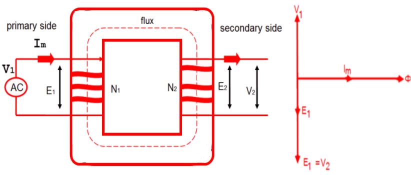
- Let us assume an ideal transformer with primary winding is connected to an AC supply and secondary winding is open-circuited i.e no load is applied to it.
- Now when an alternating voltage V1 is applied to the primary winding due to electromagnetic induction an emf E1 is induced on the primary side. Since there is no voltage drop in an ideal transformer, therefore, counter emf is equal and opposite to applied voltage V1
- Since the primary coil is pure inductive and there is no load connected to the secondary side, therefore, primary winding draws a small magnetizing current Im.
- In case of pure inductance the current lags behind the applied voltage by 90o
- This magnetizing current produces flux Φ which is directly proportional to current and therefore in phase with it.
- The flux passes through both the primary and secondary winding of the transformer so according to Faraday’s law of electromagnetic induction, the voltage V2 gets induced in the secondary winding. This V2 produced a counter emf E2 (mutually induced emf)
- At any instant (if the turns ratio is the same) the value of V1 is always equal to V2 in case of an ideal transformer.
- Both the emf E1 and E2 always lag behind the flux by 90o and their magnitudes depend upon the rate of change of flux and number of turns in the primary and secondary winding.
Note: As shown in the figure the emf E1 and E2 are in phase but E1 is equal to V1 and hence they E1 and V1 are 180o out of phase with each other.