
Measurement of Earth resistance Questions and Answers
1. What is the main purpose of earthing?
- Provide path for leakage current
- Provide electric shock safety
- Provide constant line voltage
- All of the above
Answer.4. All of the above
Explanation:-
Earthing means setting up an electrical bond between a given point in a network, installation, or machine and an earth electrode. This earth electrode is a conductive part that may be inserted in the ground or in a conductive medium, in electrical contact with the Earth.
Purposes of Earthing
- It provides a surface around and under a sub-station, which would be at a uniform potential and as near to zero or absolute earth potential as possible.
- Ensure people in the surrounding area are not exposed to electric shock.
- Better performance of the electrical system.
- To protect the human being from disability or death from shock in case the human body comes into the contact with the frame of any electrical machinery, appliance or component, which is electrically charged due to leakage current or fault.
- To maintain the line voltage constant. To serve as the return conductor for telephone and fraction work.
- Earthing enables leakage currents to flow away safely and, if it is linked to an automatic cut-off device, can ensure that the power supply to the electrical installation is switched off.
2. The earth resistance can be measured by
- Fall of potential method
- Using an earth tester
- Only (1) and (2)
- Ducter ohmmeter method
Answer.3. Only (1) and (2)
Explanation:-
Fall-of-Potential Method
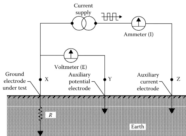
- This method measures grounding electrode resistance based upon the principle of the potential drop across the resistance.
- It also uses two auxiliary electrodes (one current rod and the other a potential rod) that are placed at a sufficient distance from the test electrodes; a current of known magnitude is passed through the electrode under test and one of the auxiliary electrodes (current rod).
- The drop in potential between the electrode under the test and the second auxiliary electrode (potential rod) is measured.
- The ratio of voltage drop (V) to the known current (I) will indicate the resistance of the grounding circuit. Either a DC or AC voltage source may be used for conducting this test.
Earth tester
- The earth resistance can be measured with the help of Earth tester or a Megger Earth Tester.
- This instrument is used for measuring the resistance of earth electrodes and the resistivity of soil. The preferred model is the 4-terminal type. It gives ac output.
- It is a combined cross-coil ohmmeter (ratio-meter) and hand-driven generator of a special type so designed that alternating current is passed on to the soil while direct current is passed through the measuring instrument.
- This instrument usually has a voltage range of 10-110 V with a current range up to 5 mA, frequency of about 92-95 Hz, ohmic range from 0-2 up to 10,000 ohms. Indigenous designs are available in the test voltage range of 50-200 V approximately.
3. In megger earth tester current and potential coils of the ohmmeter are supplied with _______ and the testing circuit is supplied with _______
- DC, AC
- AC, DC
- DC, DC
- AC, AC
Answer.1. DC, AC
Explanation
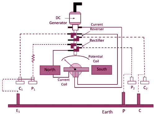
The earth tester is a special type of ohmmeter which sends ac through earth and de through the measuring instruments as shown in Fig. The direction of flow of current in the ground keeps on alternating due to current reverser whereas current direction in the two crossed coils of ohmmeter remains the same due to potential reverser. The current reversal and potential reversal are mounted on the main shaft of the hand-driven dc generator.
The ohmmeter consists of two coils mounted at a fixed angle to one another on a common axle and moving in the field of a Permanent Magnet (PM). A current proportional to the total current flowing in the testing circuit passes through the Current Coil (CC), while the Potential Coil (PC) carries a current proportional to the potential drop across the resistance under test. The cross-coil system makes the instrument a true ohmmeter giving readings in ohms that are independent of the applied voltage, speed of rotation, and contact resistance of the ground rods.
Direct current from the generator passes through the current coil of the ohmmeter to a rotating current reverser driven from the generator handle. The alternating current is thus delivered to the current terminals (the common terminals C1 and C2) of the instrument which are connected to the contact under test and to the “current” temporary earth connection. The potential coil of the ohmmeter obtains its supply from the potential terminals (common terminal P1 and the terminal P2), the latter being connected to the ‘potential’ temporary earth connection.
Since this supply is taken from the “soil” section of the current circuit and is, therefore, alternating, it must be made unidirectional before passing through the potential coil. A commutator mounted on the same shaft as the main current reverser and synchronized with it, is, therefore, interposed as a rectifier between the potential terminals and potential coil.
In this manner, both the current and potential coils of the ohmmeter are supplied with direct current. But the ‘soil’ section of the testing circuit is supplied with alternating current.
In this manner, both the current and potential coils of the ohmmeter are supplied with direct current. But the ‘soil’ section of the testing circuit is supplied with alternating current.
4. Which of the following error encountered on the fall of potential method
- Inaccurate voltmeter reading
- High power requirement
- Can use only DC voltage source
- Can use only AC voltage source
Answer.1. Inaccurate voltmeter reading
Explanation:-
Several problems and errors may be encountered with the fall of the potential methods, such as
(i) Stray currents in the earth may cause voltmeter readings to be either high or low
(ii) The resistance of auxiliary electrode and electrical leads may introduce errors in the voltmeter reading.
This error can be minimized by using a voltmeter of a high impedance value.
5. Three-point method is also known as
- Megger tester
- Megger earth tester
- Fall of potential method
- Ratio Method
Answer.3. Fall of potential method
Explanation:-
The ground resistance can be measured using a technique known as the fall-of-potential method. The method, which is also known as the three-point test.
The setup consists of the object whose ground resistance is to be determined, a current electrode, and a potential probe. The electrode is a small copper rod that is driven into the soil. A voltage source is connected between the object and the current electrode. A voltmeter is connected between the object and the potential probe.
6. Four-point method is also called as
- Megger tester
- Megger earth tester
- Fall of potential method
- Wenner Method
Answer.4. Wenner Method
Explanation:-
To measure earth resistivity, a four-terminal instrument is used, along with four small-sized electrodes driven down to the same depth and equal distances apart in a straight line. Four separate lead wires connect the electrodes to the four terminals on the instrument, as shown. Hence the name of this test: the four-terminal method.
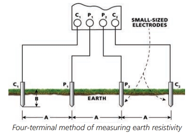
Small electrodes are inserted into four small holes in the earth all to a depth of b meters and spaced along a straight line at intervals of meters, and making electrical contact with the earth only at the bottom. A test current I is injected through the earth between the two outer electrodes and the potential E between the two inner electrodes is measured with a potentiometer or high-impedance voltmeter. The ratio between the observed potential and the injected current is referred to as the apparent resistance, which is a function of soil resistivity and the electrode geometry. The apparent soil resistivity is computed by multiplying the apparent resistance by a geometric multiplier. The apparent soil resistivity down to a depth equal to a S.
If the electrode depth (B) is kept small compared to the distance between the electrodes (A), the following formula applies:
ρ = 2πAR
where
ρ is the average soil resistivity to depth A in ohm-cm,
A is the distance between the electrodes in cm,
R is the Megger earth tester reading in ohms.
7. The earth resistivity is measured in
- Ohm
- Mho
- Ohm-cm2
- Ohm-cm
Answer.4. Ohm-cm
Explanation:-
The term “earth resistivity” expressed in ohm-centimeters (abbreviated ohm-cm) is one basic variable affecting resistance to earth of an electrode system.
Measurements of earth resistivity are also useful for finding the best location and depth for low resistance electrodes, as well. Such studies are made, for example, when a new electrical unit is being constructed, such as a generating station, substation, transmission tower, or telephone central office.
8. Touch potential measurements are similar to
- Megger earth tester
- Four-point method
- Fall-of-potential method
- Wenner Method
Answer.3. Fall of potential method
Explanation:-
Touch potential: Touch potential is the voltage difference between a person’s arm and the feet, caused by the voltage gradient due to fault or induced current. It is assumed that the current passes through the heart and therefore this potential should be kept to near zero to safeguard personnel who might accidentally come in contact with equipment and structures in a switchyard or substations.
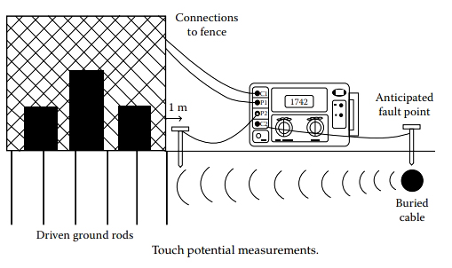
Touch potential measurements are similar to fall-of-potential measurements in that both measurements require the placement of auxiliary electrodes into or on the earth. Spacing the auxiliary electrodes during touch potential measurements differs from fall-of-potential electrode spacing, as shown in Figure.
9. Which of the following method is used for the measurement of earth resistance without the use of an auxiliary rod.
- Fall of method
- Clamp-on method
- Megger earth tester
- Any of the above
Answer.2. Clamp-on method
Explanation:-
The Ground Resistance Tester measures ground rod and small grid resistance through any season, without the use of auxiliary ground rods. Clamp-on ground resistance testers are used in multi-grounded systems without disconnecting the ground under test. The Clamp-on Ground Resistance Tester simply clamps around the ground conductor or rod and measures the resistance to the ground.
The clamp-on method measures the ground resistance based on Ohm’s law and need to have a series and parallel resistors. In this method, two clamps namely voltage and current transformers are used. During measurement, these two clamps connect either with the earth electrode or connecting cables with a separation distance of more than a 4 inches. as shown in Fig.
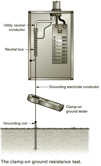
The clamp-on ground resistance tester, Figure 1-11, contains two transformers. One transformer induces a small fixed voltage at approximately 2 kHz on the grounding conductor. If a path exists, the voltage will result in a current flow. The path is provided by the grounding system under test, the utility neutral, and the utility grounding system. The second transformer inside the meter senses the amount of current at the unique frequency provided by the first transformer. The amount of current is proportional to the induced voltage and the resistance of the grounding system.
The clamp-on method is a new method to measure the ground resistance of a grounding system where many electrodes are connected in parallel. This method eliminates the dangerous and time consuming activity to disconnect the grounding system. The clamp-on method is fast and easy as no probes need to be inserted into the soil. This method of measurement is not suitable for a single or an isolated grounding system as there is no return path for the current. This method is also used for the measurement of the ground resistance inside of the substation building.
10. Which of the following are the advantages of the clamp-on ground method as compared to the fall of the potential method
- Fast & easy method for quick measurement of earth resistance
- No need to disconnect service grounding
- No need for auxiliary grounding
- All of the above
Answer.4. All of the above
Explanation:-
The clamp-on ground resistance test requires the use of a special clamp-on ground resistance meter. This test has several advantages over the three-point fall-of-potential test.
(i) The clamp-on ground method eliminates the dangerous and time-consuming activity to disconnect the grounding system.
(ii) The clamp-on method is fast and easy as no probes need to be inserted into the soil.
(iii) The service grounding system does not have to be disconnected and isolated from the neutral bus.
(iv) There are no probes that have to be driven into the ground or long connecting conductors.
(v) The neutral conductor supplied by the utility company ties innumerable grounds together in parallel. The clamp-on ground tester measures the effective resistance of the entire grounding system.
(vi) Because this test is performed by a clamp-on meter, there are no connections that have to be broken or reconnected, resulting in a safer procedure.
11. Which of the following is/are limitations of the clamp-on ground method?
- Should have multiple parallel-ground
- Not suitable for isolated ground
- Both 1 & 2
- None of the above
Answer.3. Both 1 & 2
Explanation:-
(i) The clamp-on ground method of measurement is not suitable for a single or isolated grounding system as there is no return path for the current.
(ii) Clamp ground testers effectively make loop resistance measurements. Clamp measurements are loop measurements. For the clamp method to work, there must be a series-parallel resistance path (and the lower the better).
(iii) The clamp-on method is only effective in situations with multiple earthing electrodes are in parallel and a closed circuit is available for the current circulation.
(iv) This method does not give the actual value of the ground resistance if the clamps are placed at the bonded lightning protection system.
(v) It may also give a very low reading due to the interaction of two buried water pipes and conduits.
(vi) It cannot be used on isolated grounds, thus making it in-applicable for installation checks or commissioning new sites.
(vii) Measurement of low earth resistance of the order of 0.5 ohms is difficult with this method.
(viii) The internal diameter of the clamp is usually small of the order of 25 mm which prevents the measurement of earth rods greater in size.
12. _______ method uses a Wheatstone bridge or an ohmmeter to measure the series resistance of the grounding electrode and the auxiliary electrode.
- Ratio Method
- Fall of potential method
- Megger earth tester
- Clamp Method
Answer. 1. Ratio Method
Explanation:-
The ratio Method uses a Wheatstone bridge or an ohmmeter to measure the series resistance of the grounding electrode and the auxiliary electrode.
A slide wire potentiometer is used with a Wheatstone bridge for this test. The potentiometer is connected across the grounding electrode under test and the first auxiliary electrode. The sliding contact of the potentiometer is connected to the second auxiliary electrode through a detector for determining the null point.
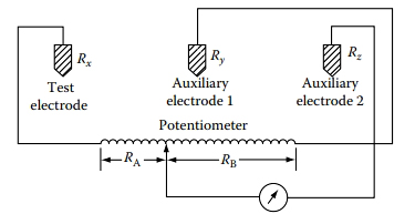
The resistance of the test electrode and first auxiliary electrode is measured first by the Wheatstone bridge or ohmmeter. Then, using the potentiometer and Wheatstone bridge, a new null point is determined with the second electrode in the test circuit. The resistance of the grounding electrode is the ratio of the test electrode resistance to the total resistance of the two in series.
As this method is a comparison method, the ohmic readings are independent of the test current magnitude. The test current magnitude can be kept high enough (few tens of milli-amps) to give adequate sensitivity.
13. The extension of fall of potential method is also known as
- 70% method
- 50% method
- 62% method
- 100% method
Answer.3. 62%
Explanation:-
The 62% method is an extension of the fall-of-potential method and has been adopted after graphical consideration and after the actual test. It is the most accurate method but is limited by the fact that the ground tested is a single unit. This method applies only when all three electrodes are in a straight line and the ground is a single electrode, pipe, or plate, etc.
This adaptation is often referred to as the 62% Method, as it involves positioning the inner test stake at 62% of the earth electrode-to-outer stake separation (recall that in the Fall-of-Potential method, this figure was 50%).
When using this method, it is also advisable to repeat the measurements with the inner test stake moved t10% of the earth electrode-inner test stake separation distance, as before.
The main disadvantage with this method is that the theory on which it is based relies on the assumption that the underlying soil is homogeneous, which in practice is rarely the case. Thus, care should be taken in its use and a soil resistivity survey should always be carried out. Alternatively, one of the other methods should be employed.
14. The voltage range of the earth tester is usually
- 10-110V
- 50-500 V
- 10-20 V
- 50-100 V
Answer.1. 10-110 V
Explantion:-
Earth tester instrument usually has the voltage range of 10-110 V with a current range up to 5 mA, frequency of about 92-95 Hz, ohmic range from 0-2 up to 10,000 ohms. Indigenous designs are available in the test voltage range of 50-200 V approximately.
15. The slope method for measurement of ground resistance is usually employed in
- Distribution System
- Residential area
- Large Substation
- Any of the above
Answer.3. Large substation
Explanation
The slope method is usually used to measure the ground resistance at any substation where a large grounding system is installed. Sometimes, it is difficult to get the flat section of the measured ground resistance versus the distance to the potential probe from the earth electrode. This situation is generally happening when the potential and the current probes are always within the zone of the influence of the earth electrode under test.
In this measurement method, the current probe needs to be placed 300 ft away from the earth electrode while the potential probe is placed at a distance of 30 ft away from the earth electrode. Afterward, the potential probe distance is varied in a step of 30 ft and the ground resistance is measured in each step.
The additional measurement and calculation effort tend to relegate this system to use with only very large or complex grounding systems.