Induced EMF Equation in Synchronous Machine
Emf is induced in the armature windings due to the cutting of flux by the rotation of the rotor poles. Distribution of coils in the stator slots and the use of short-pitch coils affect the magnitude and the waveshape of the induced coil.
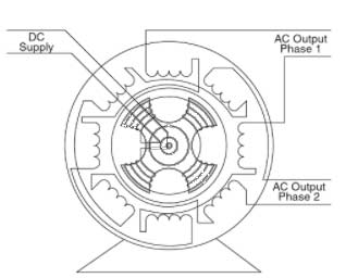
- In synchronous machines, the armature winding is made on the stator. The rotor consists of magnetic poles excited by the D.C field current.
- The rotor poles are rotated by a prime-mover through a steam turbine or a water turbine. The poles when rotating will induce emf in the armature coils because the magnetic lines will cut the coil sides as shown in the figure.
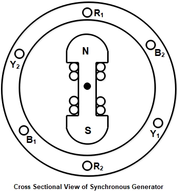
- The emf induced in phases R1 – R2, Y1 – Y2 and B1 – B2, will be identical but will have a time phase difference of 120°.
- The phase difference of 120° is the same as the time taken by the rotor to rotate by 120° electrical degrees. The generated voltages in the R, Y and B phases can be expressed as
er = Emsinωt
er = Emsin(ωt − 120°)
er = Emsin(ωt − 240°)
EMF Equation of Synchronous Machine
Let us assume that
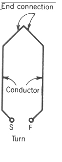
T = The number of turns in the coils connected in series in each phase.
P = The number of poles
φ = flux per pole in the webers. For a 2-pole machine, the flux cut by a conductor (coil side) in one revolution is 2 Webers and the flux cut by a conductor in one revolution of the rotor is Pφ Webers.
N = Number of rpm of the rotor. The rotor poles make N revolutions per minute (i.e. per 60 s)
Time taken by the rotor poles to make one revolution
[latex]=\frac{60}{N}s[/latex]
Average Value of induced E.M.F = Flux cut per second
[latex]\begin{array}{l} = \left( {P\phi \div \frac{{60}}{N}} \right)wb/s\\\\ = \left( {\frac{{P\phi N}}{{60}}} \right)wb/s\end{array}[/latex]
Since T is the total number of turns connected in series per phase, total number of conductors per phase = 2T= (1 turn = 2 conductor). Average emf induced per phase
[latex]{E_{av}} = \frac{{P{N_S}2T}}{{60}}{\text{ Volts}} – – – – – (1)[/latex]
If f is the frequency of induced EMF the relationship between f, P, and Ns is given by
[latex]{N_S} = \frac{{120}}{f} – – – – – – – – (2)[/latex]
From equation (1) and (2)
[latex]{E_{av}} = \frac{{P{N_S}}}{{120}} \times 4\varphi T{\text{ Volts}}[/latex]
For a sinusoidal wave, the ratio of RMS value and average value is called the form factor which is equal to 1.11
[latex]\begin{array}{l}\frac{{{E_{RMS}}}}{{{E_{avg}}}} = 1.11\\\\{E_{RMS}} = 1.11{E_{avg}}\\\\{E_{RMS}} = 1.11 \times 4\varphi fT{\text{ Volts}}\end{array}[/latex]
The E.M.F equation per phase is given as:
Eph = Eavg × Form factor
E = 4.44.φ.f.T Volts
This EMF equation is the same as that developed for transformers where the EMF in the primary and secondary windings were derived respectively as Eph1 = 4.44.φm.f.N1, and Eph2 = 4.44.φm.f.N2.
In the case of the synchronous machine, the EMF induced is called the dynamically induced EMF while in the case of the transformer the EMF induced is called statically induced EMF.
- In synchronous machines, EMF is induced due to the relative motion between the rotor flux and the stator conductors.
- In the case of transformers, EMF is induced in the winding due to the linkage of the time-varying flux with stationary coils.
- The EMF equation derived as above is to be multiplied by two factors, namely the distribution factor, Kd and the pitch factor, Kp.
With Kd and Kp into consideration, the equation for the induced EMF is
E = 4.44.φ.f.T. Kd. Kp Volts
The factor Kd is used in the EMF equation due to the use of winding being distributed rather than concentrated in two slots. The factor Kp is due to the use of short-pitch coils rather than full-pitch coils.
Distribution Factor
The distribution factor is defined as the ratio of the EMF induced in the distributed winding in a phase to the EMF induced in a concentrated winding.
Pitch Factor and Coil Span Factor
The Coil Span Factor is defined as the ratio of EMF induced in a coil when the winding is short-pitched to the induced emf in the same coil when the winding is fully pitched.