PARALLEL OPERATION OF ALTERNATOR | SYNCHRONOUS GENERATOR
When we speak about the parallel operation of alternators, the first question that arises is: what is the necessity of connecting a large number of alternators in parallel. The answer is very simple. To meet with the ever-increasing demand for electrical power, it is economical and advisable to run the number of generating units in parallel. Although a single larger unit used to meet with the demand is more economical but it reduces reliability. In fact, there are a number of good reasons to use the number of smaller units operating in parallel to meet with the existing demand. In the present scenario, not only the number of units placed at one generating station is operated in parallel as well as all the other units placed at the other generating stations which are interconnected are also operating in parallel with each other.
Necessity of Parallel Operation of Alternator
When the number of alternators is connected to the same bus-bars, they are called to be connected in parallel. In short, the requirement of parallel operation of alternator arise due to:-
- Physical size: The output power of modern power stations is so high that it is difficult to build a single unit of that capacity.
- Reliability or continuity of service: Several small units are more reliable than a single large unit because if one unit fails, the continuity of supply can be maintained by operating the other units.
- Size and cost of standby unit: Since each unit is of a smaller size, the cost of the standby unit is small. Overhauling and repairing of any small unit can be easily done.
- Extension of power plant: The additional unit can be installed as and when the load demand increases.
- Operating efficiency: Moreover, the load on the power station varies greatly both during day and night as well as during the different seasons. Then the number of units operating at a particular time can be varied depending upon the load at that time. This keeps the machines loaded upto their rated capacity and hence results in an increase in efficiency of operation as the efficiency of an electrical machine is maximum at or near rated capacity.
NOTE:- If we want to connect one alternator in parallel with other alternators already connected to the bus, we have to see that there is no disturbance created on the has and no trip-off of any unit in the circuit occurs. The process by virtue of which this connection of an alternator to the bus is made is termed synchronization.
Requirements for Parallel Operation of Alternator
When alternators are connected to parallel, they must satisfy the following conditions.
- Output voltage rating: The output voltage rating of all the alternators must be the same
- Output frequency: The rated speed of all the machines should be such that they produce the same frequency (f = PN/120).
- Output wave shape: The output waveform of all the alternators must be the same, although their kVA rating may be different. When two alternators are paralleled, not only must the rate of the rise and fall of voltage in both alternators be equal, but the rise and fall of voltage in one machine must be exactly in step with the rise and fall of voltage in the other machine.
- Speed-load characteristics: The drooping speed-load characteristics of the prime-movers of the alternators should be the same so that alternators share the load in their proportion as per their output (kVA) rating.
- Impedance triangles: The impedance triangles of the alternators should be identical for successful parallel operation.
NOTE:- The procedure of connecting an alternator in parallel with another or with a common bus-bar to which a number of alternators are already connected is called synchronizing of alternators. When two alternators are in step, they are said to be in synchronism. Alternators cannot be paralleled until their voltages, frequencies, and instantaneous polarities are nearly equal.
Conditions for Parallel Operation of Alternator
For proper synchronizing of alternators, the following conditions must be fulfilled:
- The terminal voltage of the incoming alternator must be equal to that of the bus-bar voltage.
- The voltage of the incoming alternator should be in phase opposition to the bus-bar voltage. This implies that the generator must be connected + to + and – to – hence there will be no circuiting current between the windings of the alternators already connected to bus-bars and the incoming alternator.
- The speed of the incoming alternator must be such that its frequency is equal to that of bus-bar frequency.
- In the case of three-phase alternators, the phase of the incoming alternator must be identical with the phase of the bus-bars. In other words, the phase sequence of the incoming alternator must be the same as that of the bus-bars.
If Conditions of parallel operation of the alternator is not matched
Before studying the practical method of synchronizing the alternators, we must be clear about the situation that will arise if the above conditions are not achieved. Considering only two single-phase alternators connected to the common bus-bars operating in parallel as shown in Fig. A load is connected to the bus-bars. Under these conditions, the operation of the alternators is governed by the following two factors.
- The variation of the driving torque of the prime-movers of alternators by varying steam supply.
- The variation of field current of the alternators.
Note:- There are two circuits to which current can be supplied by the alternators. One circuit is the external load(i.e the relation between the bus voltage and load current it supplies) and the other is the local internal circuit( i.e., the synchronous impedance of the two alternators or impedance generated within a single generator).
Effect of Unequal Terminal Voltages & Bus bar voltage
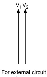
- For the external circuit (i.e., load), the terminal voltage of the two alternators is equal and in phase with each other as shown in Fig. and the alternators share the load current as per their respective ratings.
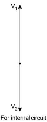
- Considering the first and the second conditions, for correct synchronizing, the terminal voltage of the incoming alternator must be equal and opposite (180° out of phase) to the voltage of the alternator already connected to the bus-bars with respect to the internal circuit as shown in Fig. Thus the resultant voltage is zero and no current circulates in the internal circuit.
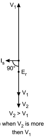
- But if these conditions are not fulfilled i.e., the two voltages are not equal to each other in magnitude as shown in Fig. a resultant voltage Er appears which will result in a circulating current Is in the local circuit. This circulating current lags behind the resultant voltage Er by 90° since the opposition of the local circuit is only due to the synchronous reactance of the two alternators as resistance is neglected.
- Another condition can be when the voltage of the second alternator is equal to the bus-bar voltage in magnitude but it is not out of phase by 180°, as shown in Fig. In this case, also a resultant voltage Er acts to circulate current Is, in the internal circuit of the alternators.
Effect of Unequal Supply frequency
For correct synchronizing, the frequency of the incoming alternator must be the same as that of the frequency of the alternator already connected to the bus-bars i.e., the vectors representing the two voltages must rotate at the same speed. But if this condition is not fulfilled, one of the vectors rotates at speed higher or lesser than the other vector (say vector V, is rotating at a speed higher than vector Vi). The position of the two vectors at different three instants is shown in Fig. 7.3. Thus, the voltages of the two alternators will come in phase and go out of phase. This will happen at the rate equal to the difference of the frequencies of the two alternators. Because of this for local circuit, the resultant voltage E, varies from zero to double the voltage (VI + V2) and circulates variable current in the local circuit.