1. Which of the following are examples of measurement of high resistance.
Insulation resistance
Leakage resistance
Vacuum tube circuit
All of the above
Answer.4. All of the above
Explanation:-
MEASUREMENT OF HIGH RESISTANCE
We knew that the resistance with a value above 100 kΩ is considered as high resistance. The measurement of high resistance of the order of hundreds and thousands of megaohms is often required in electrical equipment. The example of such resistances are as follows:
(a) The insulation resistance of various components like machines and cables.
(b) Voltage coefficient testing of resistors and leakage resistance measurements of capacitors
(c) Resistance of high circuit elements like vacuum tube circuits.
(d) Volume resistivity of a material, i.e, the resistance between two faces of unit area separated by unit distance with all conduction from face to face is through the body of the materia.
(e) Surface resistivity, i.e., the resistance between two lines of unit length and unit distance apart, the lines being on the surface of the material and all conduction being on the surface.
2. Which among the following is not a method for measurement of High Resistance?
3. Which of the following method is most widely used for insulation resistance of the cable
Loss of charge method
Mega Ohm bridge method
Direct deflection method
None of the above
Answer.3. Direct deflection method
Explanation:-
The direct deflection method is used for high resistance measurement. In such method, a high resistance about 1 kΩ or more) and very sensitive moving coil galvanometer is connected in series with the resistance to be measured along with supply voltage as shown in Fig.
The deflection of the galvanometer gives a measure of the insulation resistance. This method is widely used for measuring the insulation resistance of the cable.
4. Which of the following cable insulation resistance can be measured by the direct deflection method?
Cable with Sheath
Cable without sheath
Both 1 and 2
None of the above
Answer.3. Both 1 and 2
Explanation:-
The direct deflection method is used for the measurement of the insulation resistance of the cable. The cable can be of two types
Cable with sheath
Cable without sheath
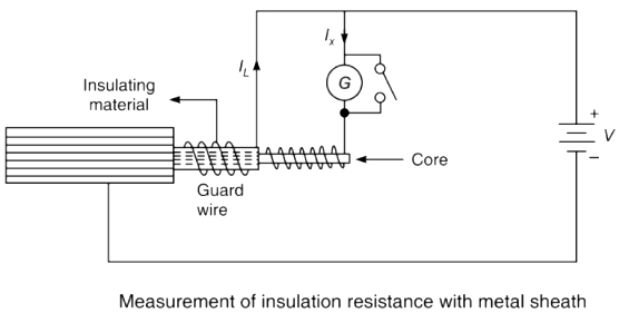
(a) Direct deflection method for Cable with Sheath
Fig. shows the direct deflection method for measuring the insulation resistance of a cable with a sheath. The galvanometer measures the current Ix between the conductor and the metal sheath. The leakage current IL, over the insulating material is carried by the guard wire wound on the insulation and therefore does not flow through the galvanometer.
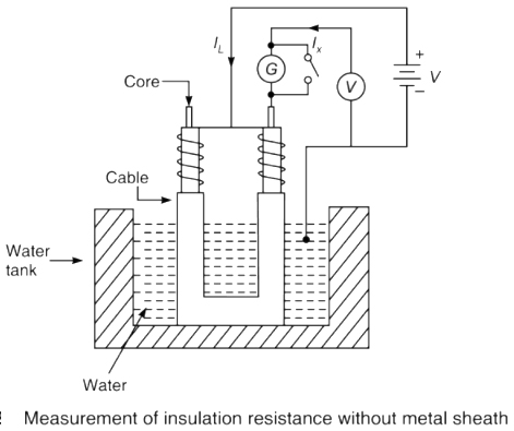
(b) Cable without Sheath:- Cables without metal sheaths can be tested in a similar way like in cable with sheath. The direct deflection method for measuring the insulation resistance is shown in Fig. First, the cable is immersed in slightly saline water for about 24 hours and the temperature is kept constant at about 20°C. The water enters the pores of the cable and the temperature of the cable attains the temperature of the water. The water and tank then form the return path for the current.
5. The direct deflection method uses the principle of
Ammeter-Galvanometer Method
Ammeter-Voltmeter Method
Shunt-capacitor method
Null Method
Answer.2. Ammeter-voltmeter method
Explanation:-
This method basically uses the principle of the ammeter-voltmeter method. The microammeter is replaced by a highly sensitive galvanometer.
A shunt is included in the circuit for the protection of the galvanometer and also to provide several ranges. The deflection of the galvanometer indicates the value of the insulation resistance under test.
A test-short switch is connected to the circuit so that when a specimen having capacitance such as a length of a cable, is tested by this method, it can be discharged easily after the measurement.
6. Which of the following statement is incorrect while taking precautions for testing the cable using the direct deflection method?
Low-value resistance should be used with a galvanometer
Galvanometer should be properly shunted
Galvanometer should have high resistance
The cable should be immersed for 24 hours
Answer.1. Low-value resistance should be used with a galvanometer
Explanation:-
(a) The direct deflection method is used for the measurement of the insulation resistance of the cable. Following precautions should be taken while using the direct deflection method.
(b) Before testing the cable is immersed in water at least for 24 hours. The temperature of the water is maintained constant. The water enters through the pores if any, and soaks through the defects, and at the same time, the cable attains the temperature of the water.
(c) In the earlier phase of the measurement, the galvanometer must be properly shunted. It includes a series resistance of high value. The true value of insulation resistance can be determined by subtracting the value of series resistance from the observed resistance.
(d) While conducting tests on cables the galvanometer should be short-circuited before applying the voltage. The short-circuiting connection is removed only after sufficient time has elapsed so that charging and absorption currents cease to flow.
(e) After the application of voltage, a short circuit connection across the galvanometer is removed. Thus galvanometer is protected from the sudden initial spike of current which charges cable which acts as a capacitor.
(f) The battery voltage should be around 500 V and should be maintained constant. The galvanometer should be highly sensitive (not less than 1000 mm per microampere at a scale distance of 1 metre), should have high resistance and also that its deflection should be directly proportional to the current flowing through it and should be critically damped.
(g) To prevent leakage currents, the galvanometer circuit switches and circuitry must be well insulated.
7. In loss of charge method _______ is connected in parallel with the insulation _______ under test.
Capacitor, Resistance
Inductor, Resistance
Inductor, Capacitor
None of the above
Answer.1. Capacitor, Resistance
Explanation:-
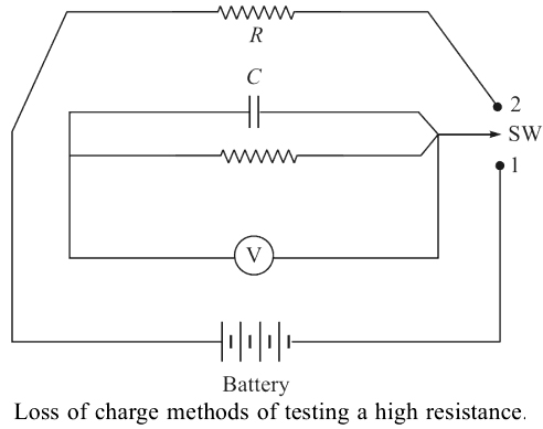
Loss of Charge Method
In the loss of charge method, a known capacitor is connected in parallel with the insulation resistance under test and an electrostatic voltmeter as shown in Figure. The capacitor is charged to a suitable voltage through a battery by throwing the switch SW to contact 1 and is then allowed to discharge through the insulation resistance under test by throwing the switch SW to contact 2. The terminal voltage across the capacitor is noted during the discharging of the capacitor over a considerable period of time.
The voltage across parallel combinations is measured using an electrostatic voltmeter. If the value of resistance R is very large, then capacitor C requires more time for discharging. In such cases, the process becomes time-consuming. This method can be used effectively for the measurement of high resistances, but it needs a capacitor with a high leakage resistance.
8. Which of the following is/are drawbacks of the loss of charge method?
Current doesn’t depend on the insulation resistance
Insulation resistance depends to a greater extent on the application of the voltage.
Effect of temperature on insulating material
All of the above
Answer.4. All of the above
Explanation:-
The loss of charge method has certain serious drawbacks and these are as follows:
(i) The current actually flowing, does not depend upon the insulation resistance alone. Due to the absorption effect in the dielectric of the capacitor, a small absorption current also flows through the insulation. This absorption current decays very rapidly at first but afterwards, this decay is very slow, therefore, observations must be continued for a longer period in order to attain high accuracy in measurement.
(ii) In the rubber-covered cables this absorption current is large, about 5-6 times the leakage current and is dependant only on the resistance after the application of the input voltage for 1 min and is equal in value to the true leakage current even after 7 min. It has been observed that the absorption current is about 5% to 10% of the total current flowing through the insulation after the voltage has been applied for 6 to 7 hours. Therefore, the insulation resistance depends to a greater extent on the time interval of application of the voltage. In commercial testing, the time of application of the voltage is normally not more than 1-2 min and therefore, from the foregoing discussion it is clear that the insulation resistance so obtained will be much less than the actual value.
(iii) The resistance of the insulating materials decreases with the increasing temperature and in some materials, this drop is very rapid. Therefore, it is important that while stating the results of insulation resistance measurements, the temperature must be specified at which the measurements have been carried out.
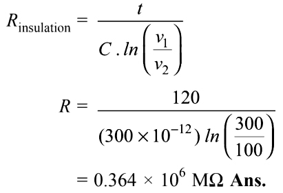
9. A length of cable was tested for insulation resistance using the loss of charge method. A capacitance formed by the sheath of cable of 300 pF is found to have a drop-in voltage from 300 V to 100 V in 120 seconds. What will1. be the insulation resistance of the cable.
0.84 × 10⁶ MΩ
0.364 × 10⁶ MΩ
0.182 × 10⁶ MΩ
0.112 × 10⁶ MΩ
Answer.2. 0.364 × 10⁶ MΩ
Explanation:-
10. The _____ is the resistance between opposite edges of a square area of the surface of the material.
Surface resistivity
Volume resistivity
Surface conductivity
Current Resistivity
Answer.1. Surface resistivity
Explanation
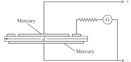
The surface resistivity is the resistance between opposite edges of a square area of the surface of the material. It depends largely on the condition of the surface and upon humidity and therefore it is not constant under all conditions of the weather. In order to measure the surface resistivity, the sample is kept in a pool of mercury as shown in Figure.
To measure the surface resistivity the galvanometer is placed as shown in Fig. The galvanometer measures the leakage current. The current flowing between the upper and lower electrodes will be eliminated from the measurement.
The negative terminal of the battery is connected to the pool of mercury. This mercury pool is contained in an annular groove to which the positive terminal of the battery is connected. A pool of mercury is also provided inside the specimen and a wire from this is connected to the positive terminal of the battery. This wire acts as a guard wire and prevents the leakage current which passes through the body of the specimen, from passing through the galvanometer.
11. If the insulation resistance material is available in sheet form. In such case which method is used for the measurement of resistance
Volume resistivity
Surface resistivity
Both 1 and 2
None of the above
Answer.3. Both 1 and 2
Explanation:-
The insulation resistance material is available in sheet form. In such case volume and surface resistivity of the material are measured as discussed below:
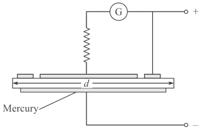
Volume resistivity is defined as the specific resistance of the material. In order to determine the volume resistivity of the insulating material, the galvanometer is connected in series with the upper electrode having diameter as shown in Figure.
Leakage current over the edge of the specimen will flow between the ring and the lower electrode and hence will not introduce error into the measurement.
The surface resistivity is the resistance between opposite edges of a square area of the surface of the material. It depends largely on the condition of the surface and upon humidity and therefore it is not constant under all conditions of the weather. In order to measure the surface resistivity, the sample is kept in a pool of mercury as shown in Figure.
To measure the surface resistivity the galvanometer is placed as shown in Fig. The galvanometer measures the leakage current. The current flowing between the upper and lower electrodes will be eliminated from the measurement.
12. Which of the following method is used for removing the leakage current from bridges.
Loss of charge method
Mega Ohm bridge method
Direct deflection method
None of the above
Answer.3. Mega ohm bridge method
Explanation:-
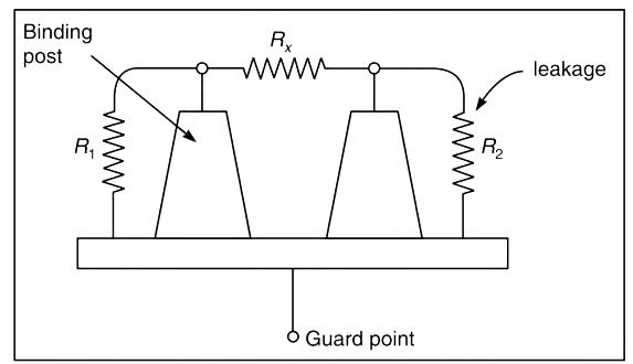
The Megohm bridge is used to remove the leakage current from bridges. This is done with the help of three terminal resistance as shown in the Fig.
The high resistance is connected between two binding posts which are fixed to the metal plate. The two main terminals of the resistor are connected to the R, terminals in the bridge. The third terminal is the common point of resistances R1 and R2, which represent the leakage paths from the main terminal along with the insulating post of the metal plate. The guard is connected to the guard terminal on the front panel of the bridge.
13. The problem faced while measuring high resistance is/are
Leakage current
Stray charge
Requirement of high voltage
All of the above
Answer.4. All of the above
Explanation:-
Problems in Measurement of High Resistance
There are some problems and difficulties that occurred in the measurement of high resistance. Due to very high resistance, a very small current flows through the measuring circuits, which is very difficult to sense. The various problem and difficulties are as follows:
1. Leakage Currents: The leakage current is produced and is of comparable magnitude to the current being measured. Such currents cause errors. These currents depend on humidity and hence are unpredictable. Hence leakage currents must be eliminated from the measurement.
2. The stray charges may appear due to the electrostatic effect such charges and alternating fields can also cause serious measurement errors.
3. One point of the circuit may be connected to the earth for accuracy in measurements.
4. When the voltage is applied to the insulation resistance, it takes some time for charging and absorbing currents. The measurement should be delayed till these current vanish completely. In some cases, this may take a very long time hence the testing conditions include the time between the application of voltage and the observation of the reading.
5. A very high voltage is required in order to raise the current magnitudes. The galvanometer should be very sensitive and proper steps must be taken to prevent the damage of the galvanometer due to high voltages.