
RC snubber circuit is used to limit the rate of
Right Answer is:
Rise of voltage across SCR
SOLUTION
Thyristor protection or SCR Protection
The transient overvoltages can switch on the thyristor. In some cases, the thyristor can be damaged due to these transient voltages. These transient voltages are very common when the converter is having inductive loads.
Snubber circuit: The thyristors can be protected against transient voltages by an RC network This RC network is connected in parallel across the thyristor. It is called a snubber circuit.
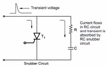
Fig. shows a snubber(RC) circuit. The resistance has a value of a few hundred ohms. Whenever there is a large spike or voltage transient across the thyristor, it is absorbed by the RC circuit. The RC circuit (snubber) acts as a lowpass filter for this voltage transient. A low-pass filter (LPF) is a filter that passes signals with a frequency lower than a certain cutoff frequency and attenuates signals with frequencies higher than the cutoff frequency.
The resistance has a normally low value so that the transient is absorbed by the capacitor quickly. Thus the thyristor is protected against voltage transients. The RC snubber circuit is very commonly used for the protection of thyristors against transient voltage High-frequency voltage spikes).
If the rate of application of the forward voltage is high, a large charging current flows that may damage the junction. For proper operation of the device, the rate of rise of the forward voltage (dv/dt) must be less than the specified dv/dt limit of the device. To protect it against damage by dv/dt, suppression of voltage transients is necessary. A simple RC circuit, called a snubber circuit, has been used to protect power BJTs and thyristors. For BJTs a snubber circuit consists of a small series inductor L connected in the collector circuit, and an RC network is connected between the collector and emitter as shown in Figure. The resistor R limits the forward dv/dt when the transistor is turned on.
The figure shows the snubber circuit for a thyristor to limit the rate of rise of voltage (dv/dt). The snubber circuit with a series inductor controls the maximum rate of change of voltage and the peak voltage across the device when a sudden forward voltage is applied to it. Since a capacitor always opposes a change in voltage, a small value of capacitance in parallel with the thyristor lowers the rate of change of voltage across the thyristor. When the thyristor is commutated, the capacitor is charged to its rated value. If the thyristor is switched on, the capacitor discharges at a rate equal to the rate of change of voltage across the thyristor. A series resistor R limits the discharging current and the device is protected from large values of instantaneous current during switching. The same RC snubber network can be used to protect GTOs and triacs. The values of R and C are a function of the load, the supply, and the device used.