
Which of the following device incorporates a terminal for synchronizing purposes?
Right Answer is:
SUS
SOLUTION
The proper operation of power electronic converters with AC input voltage requires the use of synchronizing devices to accurately determine the moment when the supply voltage passes through zero. This group of power electronic converters includes thyristor and transistor-controlled rectifiers, regulators, converters for active power factor correction, matrix converters.
Silicon Unilateral Switch (SUS)
A silicon unilateral switch (SUS) is similar to a PUT (Programmable Unijunction Transistor), except for the fact that it has an internally built low-voltage avalanche diode between the gate and the cathode. The symbol for a SUS and its equivalent circuit is shown in Fig. Its anode-to cathode electrical characteristic is shown in Fig. b for no external connection to the gate terminal because of the presence of avalanche diode, SUS turns ON for a fixed anode gate voltage.
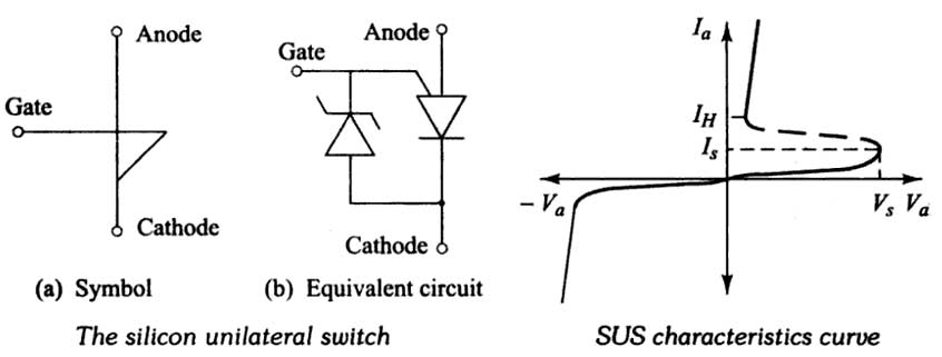
The SUS is usually used in the basic relaxation oscillator circuit. The major difference in function between the SUS and UJT in relaxation oscillator circuitry is that the SUS switches at a fixed voltage, determined by its internal avalanche diode, rather than a fraction of a smaller voltage. Also, it should be noted that the switching current is much higher in the SUS than in the UJT, and is also very close to It. These factors restrict the upper and lower limits of frequency or time delay which are practical with the SUS. For synchronization, lock-out, or forced switching, bias or pulse signals may be applied to the gate terminal of the SUS. Silicon Unilateral Switch is used mainly in timing the logic and trigger circuits. The SUS rating is about 20 V, 0.5 A. Since, the device will turn on for a fixed anode gate voltage. The device can also be used as a relaxation oscillator. The output pulses are used for triggering SCRs.
At the end of each half-cycle, each SCR will cease to conduct as the potential difference across it drops to zero and so a voltage pulse must be applied to its gate if it is required to conduct during the next half-cycle.
As an alternative to the SCR, a triac or SUS may be used. This device acts as two SCRs connected in inverse parallel and, if pulsed with an alternating supply, will conduct in both phases of the AC cycle. Like the SCR, the device will only conduct when the voltage is not at zero volts and the device has been pulsed.
During the exposure, the timer is simply required to apply a sequence of synchronized pulses to the gate of the device at a time slightly later than the mains zero to switch them back on and ensure their continued conduction. At the end of the exposure, these pulses stop, and conduction through the device stops at the end of the next half-cycle. The system allows the accuracy of one voltage pulse (i.e. an exposure time of 0.01 seconds in the case of a two-pulse unit, or 0.002 seconds in the case of a medium frequency unit.