The two-transistor model of the SCR can be obtained by:-
Right Answer is:
Bisecting the SCRs top two and bottom two layers
SOLUTION
SCR is a unidirectional device and like a diode, it allows current to flow in one direction only. It can be used as a switch. The switching of SCR is controlled by the additional input called the gate and biasing conditions. It can be used as a rectifier to convert AC signals to DC signals.
Construction
The SCR is a four-layer p-n-p-n device, where p and n layers are alternately arranged. The outer layers are heavily doped. There are three p-n junctions called J1, J2, and J3. The outer P-layer is called the anode and outer n-layer is called the cathode, middle P-layer is called the gate. The terminals are taken out from their layers. The anode must be positive with respect to the cathode so that SCR will be forward-biased. To turn on an SCR, a current is to be passed through the gate terminal. Hence it is a current operated device.
Two Transistor Model of SCR
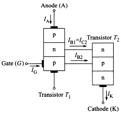
The operation of an SCR can also be explained in a very simple way by considering it in terms of two transistors. This is known as the two transistor analogy of the SCR. The SCR can be considered as an NPN and a PNP transistor, where the collector of one transistor is attached to the base of the other and vice versa. This model is obtained by splitting the two middle layers of the SCR into two separate parts.

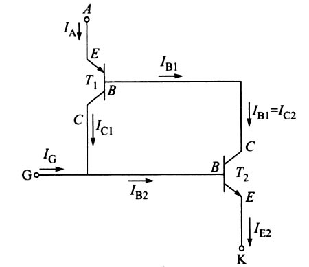
In the above figure, two middle layers of the SCR is split into two separate parts i.e PNP transistor T1 and NPN transistor T2. Collector current in the NPN transistor acts as the base current for the PNP, and analogously, the collector current of the PNP acts as the base current driving the NPN transistor.

IA is the anode current
IC is the cathode current
IG is the gate current
IE1 is the emitter current of the PNP transistor (T1)
IE2 is the emitter current of the NPN transistor (T2)
IC1 is the collector current of the PNP transistor (T1)
IC2 is the collector current of the NPN transistor (T2)
IB1 is the base current of the PNP transistor (T1)
IB2 is the base current of the PNP transistor (T2)
α1 is the current gain of the transistor T1
α2 is the current gain of the transistor T2
The sum of two collector currents is equal to the external circuit current Ia, entering at anode terminal A.
∴ Ia = IC1 + IC2
