Auto transformer basics
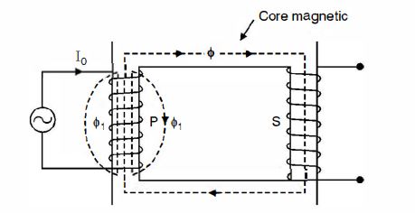
Normal transformers have two winding placed on two different sides i.e. primary and secondary. In Auto Transformer, one single winding is used as primary winding as well as secondary winding i.e primary and secondary shares the common single winding. The primary is electrically connected to the secondary, as well as magnetically coupled to it. Auto transformers are often used to step up or step down voltages up to 240 V range.
An auto transformer has a single winding with two end terminals and always having one terminal in common with the primary voltage. The primary voltage is applied across two of the terminals, and the secondary voltage is taken from two terminals. The auto transformer develops a voltage in proportion to its number of turns since the volts-per-turn is the same in both windings. In an auto-transformer part of the current flows directly from the input to the output and the remaining part is obtained by transformer action, therefore, an auto transformer work a the voltage regulator.
Auto transformer working
The winding AB is called as primary winding having total turn N1. The winding is tapped from the point C as shown in the figure, now the winding BC becomes secondary winding having the number of turns N2.
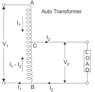
Let V1 voltage is applied across “A & C”
Therefore voltage per turn in the winding is = \(\frac{V_{1}}{N_{1}}\)
And the voltage across the “B&C” of the winding is = \(\frac{V_{1}}{N_{1}}×N_{2}\)
This \(\frac{V_{1}}{N_{1}}×N_{2}\) is equal to voltage V2 as shown in the figure.
Hence, \(\frac{V_{1}}{N_{1}}×N_{2}=V_{2}\)
If no-load current and iron losses are neglected then
⇒\(\frac{V_{2}}{V_{1}}=\frac{N_{{2}}}{N_{1}}\) = Constant =K
Here the value of constant ′K′ is nothing but voltage ratio of the auto transformer. Load current I2 starts flowing ,when load is connected between secondary terminals i.e. between ′B′ and ′C′. The current in the secondary winding i.e “B & C” is the difference of I2 & I1 where (I2 > I1).
Saving of Copper in Auto-Transformer:
The weight of conductor for any winding depends upon two parameters:
- Current carried by the winding
- Number of turns required in the winding
Hence the weight of conductor is proportional to the product of the number of turns and current to be carried i.e MMF.
The weight of copper in auto-transformer = weight of copper in section AC + weight of copper in section CB.
⇒weight of copper in section AC ∝ (N1 – N2)I1
⇒weight of copper in section BC ∝ N2 (I2 – I1)
⇒Weight of copper in auto-transformer = (N1 – N2)I1 + N2 (I2 – I1)
⇒N1I1 – N2I1 + N2I2 – N2I1
⇒N1I1 – 2N2I1 + N2I2
⇒2N1I1 – 2N2I1 (∵ N1I1 = N2I2 )
⇒2(N1I1 – N2I1)
The weight of copper in two winding transformers is ∝ N1I1 – N2I2
∴ N1I1 – N2I2 ⇒ 2N1I1 (∵ N1I1 = N2I2 )
Let’s the weight of copper in auto transformer is (Wa)
and the weight of copper in an ordinary transformer is (Wo)
Hence \(\frac{W_{a}}{W_{o}} =\frac{2(N_{1}I_{1} – N_{2}I_{1})}{2N_1I_1}\)
⇒ \(1-\frac{N_{2}}{N_{1}}\) = 1 – K
∴Wa = Wo(1 – K)
⇒Wa = Wo – KWo
∴ Saving of copper = Wo – Wa = KWo
∴ Saving of copper = K × Weight of copper in ordinary transformer
Auto transformer advantages and disadvantages
Auto transformer advantages
⇒ auto transformer is smaller in size and cheaper
⇒Less ohmic loss and core loss due to reduction of transformer material therefore auto-transformer has higher efficiency.
⇒Voltage drop in resistance and reactance is less in single winding therefore auto-transformer has higher voltage regulation as compared to conventional two winding transformer of the same rating.
Auto transformer disadvantages
- It has no isolation between the windings, so in case of faults or transients, the effect is transferred to the other side.
- It is used for small applications, and can’t be used for heavy switching applications.
- Because of Low short circuit impedance value, short circuit currents can reach higher critical value.
- In star-star connected auto transformer have common neutral therefore it is not possible to neutral only one side of the auto transformer.
Auto transformer applications
- It is used as control equipment in for 1-phase or 3-phase electrical locomotive.
- To give the small boost to the distribution cable to correct the voltage drop.
- Auto transformer is used for starting induction or synchronous motor as it gives 50 to 60{e3f30b17d1e2ee29a456ac094afcdceaab760d87d11dd966225a50cd59ff675b} full voltage to an induction motor.