Nodal Analysis MCQ [Free PDF] – Objective Question Answer for Nodal Analysis Quiz

12. Nodal analysis can be applied to non-planar networks also.

A. true
B. false

Answer: A

Nodal analysis is applicable for both planar and non-planar networks. Each node in a circuit can be assigned a number or a letter.


13. In nodal analysis how many nodes are taken as reference nodes?

A. 1
B. 2
C. 3
D. 4

Answer: A

In nodal analysis, only one node is taken as a reference node. And the node voltage is the voltage of a given node with respect to one particular node called the reference node.


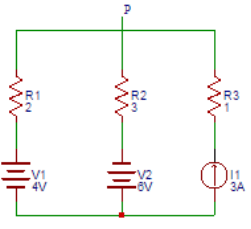
14. Find the voltage at node P in the following figure.

Find the voltage at node P in the following figure.

A. 8V
B. 9V
C. 10V
D. 11V

Answer: B

I1  = (4 − V)/2

I2  = (V + 6)/3.

The nodal equation at node P will be I1 + 3 = I2.

On solving, V = 9V.


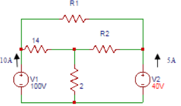
15. Find the resistor value R1(Ω) in the figure shown below.

Find the resistor value R1(Ω) in the figure shown below.

A. 10
B. 11
C. 12
D. 13

Answer: C

10 = (V1 − V2)/14 + (V1 − V3)/R1.

From the circuit,

V1 = 100V,

V2 = 15×2 = 30V

V3 = 40V.

On solving, R1 = 12Ω.


16. Find the value of the resistor R2 (Ω) in the circuit shown below.

Find the resistor value R1(Ω) in the figure shown below.

A. 5
B. 6
C. 7
D. 8

Answer: B

V1 = 100V,

V2 = 15×2 = 30V

V3 = 40V

(V1 − V2)/14 + (V1 − V3)/R2 = 15.

On solving we get R2  = 6Ω.


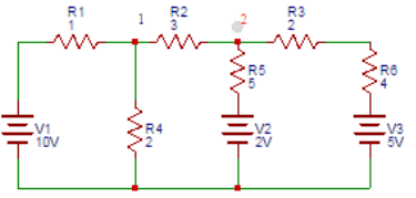
17. Find the voltage (V) at node 1 in the circuit shown.

Find the voltage (V) at node 1 in the circuit shown.

A. 5.32
B. 6.32
C. 7.32
D. 8.32

Answer: B

At node 1, (1/1 + 1/2 + 1/3)V1 − (1/3)V2  = 10/1.

At node 2, − (1/3)V1 + (1/3 + 1/6 + 1/5)V2  = 2/5 + 5/6.

On solving the above equations, we get V1 = 6.32V.


18. Find the voltage (V) at node 2 in the circuit shown below.

Find the voltage (V) at node 1 in the circuit shown.

A. 2.7
B. 3.7
C. 4.7
D. 5.7

Answer: C

At node 1, (1/1 + 1/2 + 1/3)V1 − (1/3)V2  = 10/1.

At node 2, − (1/3)V1 + (1/3 + 1/6 + 1/5)V2  = 2/5 + 5/6.

On solving the above equations, we get V2 = 4.7V.


19. Find the voltage at node 1 of the circuit shown below.

Find the voltage at node 1 of the circuit shown below.

A. 32.7
B. 33.7
C. 34.7
D. 35.7

Answer: B

Applying Kirchhoff’s current law at node 1,

10 = V1/10 + (V1 − V2)/3.

At node 2,

(V2 − V1)/3 + V2/5 + (V2 − 10)/1 = 0.

On solving the above equations, we get V1 = 33.7V.


20. Find the voltage at node 2 of the circuit shown below.

Find the voltage at node 1 of the circuit shown below.

A. 13
B. 14
C. 15
D. 16

Answer: B

Applying Kirchhoff’s current law at node 1,

10 = V1/10 + (V1 − V2)/3.

At node 2, (V2 − V1)/3 + V2/5 + (V2 − 10)/1 = 0.

On solving the above equations, we get V2 = 14V.


21. Find the value of the currents I1, I2, and I3 flowing clockwise in the

Find the value of the currents I1, I2 and I3 flowing clockwise in the

A. 1.54A, − 0.189A, − 1.195A
B. 2.34A, − 3.53A, − 2.23A
C. 4.33A, 0.55A, 6.02A
D. − 1.18A, − 1.17A, − 1.16A

Answer: A

The three mesh equations are:

− 3I1 + 2I2 − 5 = 0

2I1 − 9I2 + 4I3 = 0

4I2 − 9I3 − 10 = 0

Solving the equations, we get

I1 = 1.54A, I2 = − 0.189 and I3 = − 1.195A.

Scroll to Top