1. When the 3-phase system is not grounded and if Single Line to Ground fault occurs, the voltage of the other two healthy phases will
Increases
Decrease
Remain Unaffected
Any of the above
Answer.1. Increases
Explanation:-
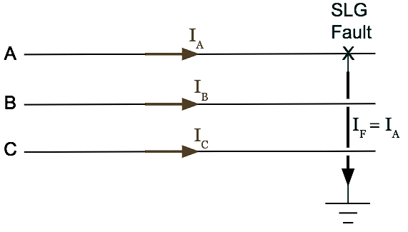
A single-line-to-ground (LG), fault occurs when one phase conductor breaks and falls to the ground or when one phase conductor comes in contact with a neutral conductor.
When the 3-ϕ system is not grounded and if the single line to ground fault occurs then the voltage increase of the unfaulted phases during a single line-to-ground fault
In a single line to ground fault in an ungrounded power system, voltages of healthy phases increase which may cause swell in those phases.
Under a single line-to-ground fault, the voltage of the faulty phase (line) becomes equal to ground voltage and the voltages of the two remaining healthy phases (lines) with respect to ground rise from their normal phase to neutral voltages to full line value (i.e., √3 times the normal phase value). This causes stress on the insulation.
2. During the system fault the voltage swell will ______ the voltage.
Decrease
Increase
Zero
None of the above
Answer.2. Increase
Explanation:-
Voltage swell: A temporary increase of voltage at a point in the network above a certain predefined threshold, typically set at 1.1 pu. These are also defined by their magnitude and duration. Voltage swells are generally associated with system faults as in the case of an increase in voltage levels in the unfaulted phases when a single line to ground fault occurs.
At the same time, these can be caused by the switching of large loads as in the case of the switching of large capacitor banks. The levels of the voltage swells are dependent on the location of the faults, system impedance, and grounding.
3. During EHV equipment maintenance, first it should be isolated and connected to the ground because
To provide a low impedance
To discharge the charging capacitance to ground
Protection for operating personnel
Both (2) and (3)
Answer.4. Both 2 and 3
Explanation:-
Grounding is generally used in three-phase systems for connecting the neutral of the system to the ground. This is done in order to avoid arcing faults which happen when the line to ground fault occurs in a system with ungrounded neutral. Here the magnitude of phase voltage becomes equal to line voltage which can cause electric discharge around the surface of the insulator creating a flashover arc.
Capacitive-Coupled Voltages:- Whenever two or more conductive surfaces (transmission line conductors and the earth) are separated by insulation (air), and one or more of such surfaces (transmission line conductors) Is energized, an alternating current will be induced in these various surfaces. steady-state charging Currents will tlow due to this capacitive effect. Although these currents are too low to operate the protective relays that would trip power circuit breakers, they are high enough to be potentially hazardous to personnel.
If a de-energized line or equipment is insulated from the ground but located near an energized line or bus, it will become charged to a potential that is above ground potential.
When personal protective grounds are applied, the insulation is shunted, and the line or bus potential drops to ground potential at that point as the capacitive charge is discharged through the ground leads.
The protective grounds, required at the Worksite to protect against accidental energization, will take care of the capacitive-charging current at the work- Site.
4. Moisture content in the soil _______ the earth soil resistance.
Increase
Decrease
Does not effect
None of the above
Answer.2. Decrease
Explanation:-
The resistivity of soil mainly depends on the content of water and the resistivity of water itself. Therefore, the resistivity of soil depends on some factors. These are the
(i) type of soil along with area.
(ii) moisture content
(iii) temperature
(iv) grain size of the material and its distribution
(v) salts dissolved in the soil
(vi) closeness of the minerals in the soil.
The moisture of the soil changes in different seasons and at different depths of the soil. The moisture content increases as the depth of the soil increases.
With the increase in moisture content, the resistivity decreases and hence soil resistance decreases.
5. Ground resistance should be designed such that
Grounding resistance should be as high as possible
Grounding resistance should be always zero
Grounding resistance should be as low as possible
None of the above
Answer.3. Grounding resistance should be as low as possible
Explanation:-
The grounding system basically provides a low resistance path for the fault and lightning currents in order to maintain the safe potential with respect to the zero potential.
High grounding resistance of more than 100 Ω often shows a capacitive type and a low resistance of less than 10Ω in the inductive type. Thus, the grounding resistance should be treated as impedance. The steady-state grounding resistance is designed to be as low as possible. In order to achieve low resistance, grounding systems are designed in a way to achieve as large as possible contact surface between the grounding system conductors and the surrounding soil.
Ideally, the ground should be of zero ohms resistance. However, the NFPA and IEEE have recommended a ground resistance value of 5.0 ohms or less. The grounding resistance is lower as the grounding electrode is larger. Therefore, high cost is required.
6. Generally grounding is provided for
Only for the safety of the equipment
Only for the safety of the operating personnel
Both (1) and (2)
None of the above
Answer.3. Both (1) and (2)
Explanation:-
The main purpose of the grounding systems is to ensure the integrity of substations equipment and the safety of personnel in and outside of substation at the maximum fault currents.
A good grounding system will improve the reliability of equipment and reduce the likelihood of damage due to lightning or fault currents.
7. Earth wire or ground wire is made of
Copper
Aluminum
Iron
Galvanized steel
Answer.4. Galvanized Steel
Explanation:-
Galvanized steel conductors do not corrode, and possess high resistance. Hence such Wires are used in telecommunications circuits, earth wires, guard wire, stray wire, etc.
8. The objective of earthing or grounding is
To provide as high resistance possible to the
T
To provide the flow of positive, negative and zero sequence currents
None of the above
Answer.2. To provide as low resistance possible to the ground
Explanation:-
The ground is a source for unwanted currents and also as a return path for the main current sometimes. While earthing is done not for return path but only for the protection of delicate equipment. Both earth and ground low resistance path for current.
When we take out the neutral for a three-phase unbalanced connection and send it to the ground, it is called grounding. Grounding is done to balance an unbalanced load. While earthing is used between the equipment and earth pit to avoid electrical shock and equipment damage.
9. Average resistance of the human body is
500 ohms
1000 ohms
1500 ohms
2000 ohms
Answer.1. 500 ohms
Explanation
The accepted minimum value of resistance for a human body is 500 ohms. While dry skin may have a resistance of 5,000 to 50,000 ohms (which can easily be checked with an ohmmeter), water or perspiration will reduce this resistance considerably. In addition, voltages above 250 volts readily penetrate the skin’s resistance. Thus, we use the average figure of 500 ohms for the body’s resistance to being on the safe side.
10. Factors on which soil resistance depends
Depth of the electrode
Moisture
NaCl
Answer.4. All of the above
Explanation:-
The resistivity of soil mainly depends on the content of water and the resistivity of water itself. Therefore, the resistivity of soil depends on some factors. These are the
(i) type of soil along with area.
(ii) moisture content
(iii) temperature
(iv) grain size of the material and its distribution
(v) salts dissolved in the soil
(vi) closeness of the minerals in the soil.
The moisture of the soil changes in different seasons and at different depths of the soil. The moisture content increases as the depth of the soil increases.
11. When earth fault occurs
The voltage potential at the earth mat increases due to grounding
The voltage potential at the earth mat decreases due to grounding
The voltage potential at the earth mat remains zero irrespective of fault
None of the above
Answer.1. The voltage potential at the earth mat increases due to grounding
Explanation:-
The substation ground mat is a series of interconnected ground wires buried in the earth of the substation floor.
The primary purpose of the substation ground is to provide electric shock protection for personnel working in and around the substation, including during lightning strokes, short circuits, equipment failures, and many situations of human error or carelessness.
Discharge through the lightning arresters into the ground mat will raise the substation ground mat potential appreciably above “remote earth.” The potential difference between the main substation and “remote earth”
Numerically, the ground potential rise is equal to the product of the grid resistance times the maximum grid current.
This protection is provided by the multiple interconnections (grounding) of all accessible surfaces within the substation in such a way as to limit to a safe level the voltage differences that can appear from point to point on these surfaces.
Increase in voltage potential at the earth mat caused by electrical faults that occur at electrical substations, power plants, or high voltage transmission lines.
When the fault occurs, short circuit current flows through the equipment and into the grounding electrode. The resistance of the Earth is non-zero, so current injected into the earth at the grounding electrode produces a potential rise with respect to a distant reference point.
There are some standards that guide the grounding of the substation.
A good grounding scheme will ensure faster fault clearing and a low enclosure potential rise.
The limitation of this method is that it does not provide protection against the traveling wave which may reach the equipment in the station.
12. The size of the earth or ground wire is based on the
Maximum fault current carrying through the ground wire
Rated current carrying capacity of the service line
Depends on the soil resistance
Both (1) and (3)
Answer.4. Both (1) and (3)
Explanation:-
Earthing is used to protect from an electric shock. It helps by providing a path for a fault current to flow to earth.
The size of the earth wire depends on
a) Maximum fault current carrying through the ground wire
b) Resistance and moisture content of soil
Earth Conductor Sizes
Steel conductors and electrodes are used for distribution line and substation grounding. The minimum conductor area required can be calculated from the following empirical formula
Area in mm2 = 12.15 × 10⁻³ I√t
where,
I= fault current in amperes
t= duration of fault current, usually taken as 3 s.
Ground conductor sizes shall be selected on the basis of maximum, three-phase, short circuit currents.
While selecting the conductor for thermal stability according to the above formula, mechanical strength and corrosion of the conductor are given due consideration.
The fault current will be almost double if two transformers of the same size are run in parallel. The conductor sizes may be calculated with due corrosion allowance and nearest standard size of steel strip or MS rod or G wire may be selected.
For a given electrode, the resistance to earth depends mainly upon the electrical resistivity of the soil in which it is installed. The soil resistivity profile on-site often determines the design of the ground electrode subsystem and the depth to which the electrode must be driven to obtain satisfactory ground resistance.
13. In high voltage systems the neutral system is _______
Not grounded
Solidly Grounded
System Grounded
Any of the above
Answer.2. Solidly Grounded
Explanation:-
The neutral grounding is an important aspect of power system design because the performance of the system in terms of the short circuits, stability, protection, etc. is greatly affected by the state of the neutral.
In most modern high voltage systems the neutral of the system is solidly grounded i.e., the neutral is connected directly to the ground without any intentional impedance between the neutral and the ground. Generally the neutral of the generator is connected through resistance to limit the stator short circuit current and also for stability reasons.
14. The advantage of neutral earthing is
Freedom from persistent arcing grounds
Overvoltages due to lightning can be discharged to the earth
Simplified design earth fault protection
All of the above
Answer.4. All of the above
Explanation:-
The advantages of neutral grounding are:
(i) Voltages of the phases are limited to phase to ground voltages.
(ii) The high voltages due to arcing grounds or transient line to ground faults are eliminated.
(iii) Sensitive protective relays against line-to-ground faults can be used.
(iv) The overvoltages due to lightning are discharged to the ground, otherwise, there will be a positive reflection at the isolated neutral of the system.
15. The advantage of operating with an isolated neutral system is
Possibility of maintaining supply even at fault
Less communication interference
Both 1 & 2
None of the above
Answer.3. Both 1 & 2
Explanation:-
The following are the advantages of operating with isolated neutral:
(i) It is possible to maintain the supply with a fault on one line.
(ii) Interference with communication lines is reduced because of the absence of zero sequence currents.
16. Which among the following is related to unsymmetrical faults?
Double line to ground fault
Single line to ground fault
Line to Line fault
All of these
Answer.4. All of these
The fault in the power system is generally categorized into two type
Symmetrical fault
Unsymmetrical fault
Symmetrical Fault
The symmetrical faults are often known as balanced faults. In the case of balanced faults, all three transmission lines are affected equally, and the system remains in the balanced condition. These types of faults are rare in the power system, and it contributes 2 % to 5 % of the total fault. These faults are easy to analyze. The symmetrical faults are classified as three lines to ground fault (LLLG) and three lines fault (LLL). The connection diagrams of symmetrical faults are shown in Fig. If the fault impedance, Zf = 0, then the fault is known as a solid or bolted fault.
Unsymmetrical Faults
The faults in the power system network which disturb the balanced condition of the network are known as unsymmetrical faults. The unsymmetrical faults are classified as the single line to ground faults (SLG), double line to ground faults (DLG 10%) and line to line faults (LL 15%). More than 90 % of faults occur in a power system are the single line to ground faults. The connection diagrams of different types of unsymmetrical faults are shown in Fig.
17. Power stations and sub-stations are protected against direct strokes of lightning using:
Rod Gap arrester
Earthing screen
Horn Gap arrester
Over Head ground wire
Answer.2. Earth Screen
Explanation
Types of Lightning Strokes
There are two main types of lightning strokes that appear on various equipment in the power system. They are viz. Direct Stroke and Indirect Stroke. Direct stroke may appear on line conductor, on tower top or on the ground wire indirect stroke may appear on overhead line conductors.
Direct Stroke on Overhead Conductors
These strokes are most dangerous as their effects are most severe and harmful. In this type of stroke, the discharge or the current path is directly from the cloud to the overhead line. From the line, the current path may be over the insulators down the pole to the ground. The voltage set up is in millions which can cause flashover and puncture of insulators. The insulators may get shattered till the surge is sufficiently dissipated and it travels to both sides. The wave may reach the substation and damage the equipment because of excessive stress produced.
The earthing screen and the ground wire provide protection against direct lightning strokes but do not provide any protection against travailing waves which may reach the electrical apparatus. The lightning arresters or the surge arresters are the ones who provide protection against the travailing waves.
Indirect Strokes
The effect of indirect strokes is similar to that of direct strokes. Their effect is more severe in the case of distribution lines than in the case of high voltage lines. These strokes are due to electrostatically induced charges on the conductors due to the presence of charged clouds. Sometimes currents may be induced electromagnetically due to lightning discharge in the immediate vicinity of the line which results in an indirect stroke.
Commonly used equipment for protection against lightning strokes is as given below.
Earthing screen.
Overhead ground wires
Lightning arresters or surge diverters.
To protect the generating stations and the substations from direct strokes, an earthing screen is used. Overhead ground wires protect the overhead transmission line from direct lightning strokes. The protection against both kinds of strokes direct and indirect in the form of travailing waves is provided with the help of lightning arresters.
Earth Screening
It consists of a network of copper conductors, earthed at least at two points, overall the electrical equipment in the sub-station. When a direct stroke occurs on the station, the screen provides a low resistance path by which Lightning surges are conducted to the ground. In this way, station equipment is protected against damage.
An Earthing Mat is the interconnection of the Horizontal and Vertical electrodes. The vertical Electrodes are for the dissipation of fault current into the ground while horizontal electrodes are laid for suppressing the dangerous Touch and Step voltages that are generated due to heavy fault current.
A substation is an assembly of large no of electrical equipment. All the equipment, as well as working personnel, must be safe even in adverse conditions.
The substation grounding system is an essential part of the overall electrical system. The proper grounding of a substation is important for the following two reasons:
2. It provides a safe environment to protect personnel in the vicinity of grounded facilities from the dangers of electric shock under fault conditions.
The grounding system includes all of the interconnected grounding facilities in the substation area including the ground grid, overhead ground wires, neutral conductors, underground cables, foundations, deep well, etc. The ground grid consists of horizontal interconnected bare conductors (mat) and ground rods. The design of the ground grid to control voltage levels to safe values should consider the total grounding system to provide a safe system at an economical cost. After the construction of Earth Mat, Crushed Gravels (of resistivity around 5000 ohms) are laid above the whole mat area. This makes the high resistive path for the dangerous voltages generated(Touch, Step Voltage), which in turn prevents a person from electric shock standing above the Earth mat area.
There are some standards that guide the grounding of the substation.
A good grounding scheme will ensure faster fault clearing and a low enclosure potential rise.
The limitation of this method A that it does not provide protection against the traveling wave which may reach the equipment in the station.
18. A system where all transformer neutrals are unearthed is called
Redirect neutral system
Ground Neutral System
Isolated neutral system
Unisolated neutral system
Answer.3. Isolated neutral system
Explanation
A system where all transformer neutrals are unearthed is called an isolated neutral system. The only intentional connection between an unearthed neutral and earth is via high impedance equipment for protection or measurement purposes such as surge arresters or voltage transformers.
In a power system there are however always capacitive connections between the phases and earth. The strength of the capacitive connection depends on the type and length of the power system circuit. When an earth fault occurs in the system, the capacitance to earth of the faulty phase is bypassed.
19. Select the correct statement of grounding and earthing
Statement 1:- Earth is used for the safety of the human body While Grounding is used for the protection of equipment Statement 2:- Grounding acts as neutral and neutral acts as a ground
Both statements are correct
Both statements are incorrect
Only statement 1 is correct
Only statement 2 is correct
Answer.3. Only statement 1 is correct
Explanation:-
(i) Earthing is used between the equipment and earth pit so as to avoid electrical shock and equipment damage. Here the outer body of the device is connected to the ground so as to provide a path to the ground for the surface charge.
(ii) Grounding is generally used in three-phase systems for connecting the neutral of the system to the ground. This is done in order to avoid arcing faults which happen when the line to ground fault occurs in a system with ungrounded neutral.
(iii) Earthing is to protect the circuit elements whenever high voltage is passed by thunders or by any other sources while Grounding is the common point in the circuit to maintain the voltage levels.
(iv) Earth is used for the safety of the human body in fault conditions while Grounding (As neutral earth) is used for the protection of equipment.
(v) Earthing is a preventive measure while Grounding is just a return path
(vi) The ground conductor provides a return path for fault current when a phase conductor accidentally comes in contact with a grounded object. This is a safety feature of the wiring system and we would never expect to see grounding conductor current flow during normal operation.
(vii) Do not Ground the Neutral Second time When It is grounded either at Distribution Transformer or at Main service Panel of Consumer end.
(viii) Grounding act as neutral. But neutral cannot act as ground.
20. Solid grounding is adopted for voltages below
100 V
200 V
400 V
600 V
Answer.4. 600 V
Explanation:-
For low voltages up to 600 volts and for high voltages above 33 kV, solid grounding is used because of the higher point-of-fault energy levels.
On system 115 kV and above additional savings are possible because the transformers with the insulation graded towards the neutral are less costly.
For medium voltages between 3.3 kV and 33 kV resistance or reactance, grounding is used.