
Resistance vs Impedance: Difference between Resistance & Impedance
Resistance and Impedance are the technical terms used in an electric circuit. In brief, the resistance controls the flow of current in either DC or A.C circuit on the other hand impedance is used to control the flow of current in an A.C circuit only. In this article, we will try to explain the difference between resistance and Impedance based on various factors like Power factor, Phase angle, measuring instrument, and many more.
Definition of Resistance and Impedance
Resistance
When an electric potential difference of ‘V’ volts is applied across the two terminals of conducting material, the free electrons of the material align in a row and reach the positive terminal of the supply (cell) promptly.
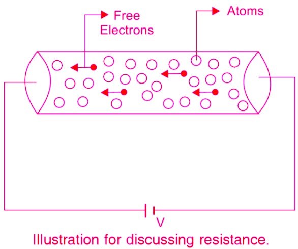
However, in doing so, the free electrons are met by other atoms of the conductor, and both these collide with each other. The collision between the free electrons and the atoms is reflected as an ‘opposition to the flow of free electrons. That is, this collision process ‘resists’ the flow of free electrons; hence it is referred to as the RESISTANCE of the material. The collision between the free electrons and the atoms contributes to power loss and is dissipated as heat by the conductor. So the basic definition of resistance is
Resistance:- The opposition to the flow of DC current caused by the nature and physical dimensions of a conductor. Resistance is represented by the symbol “R” and it is measured in ohm (Ω).
Impedance
When alternating currents flow in circuits, these circuits might exhibit additional characteristics besides resistance. They might exhibit inductive reactance or capacitive reactance or both. The total opposition offered to the flow of AC current is called Impedance. The symbol of Impedance is Z and measured in ohms.
Unlike resistive circuit, the impedance circuit consists of addition elements i.e capacitance and inductance connected in series or parallel
Since AC constantly changes direction and intensity, inductors and capacitors may also create opposition to current flow in AC circuits. The opposition offered to the flow of AC current by the inductance capacitance or both in a circuit is called reactance.
Factor affecting Resistance and Impedance
Factor affecting Resistance
The resistance of any material depends on four factors:
- The material of which it is made
- The length of the material
- The cross-sectional area of the material
- The temperature of the material
Nature of Material:-The material of which an object is made affects its resistance. The ease with which different materials give up their outer electrons is very important in determining resistance.
Length of material:- Length also affects the resistance of a conductor. The longer a conductor, the greater the resistance. A material resists electrons’ flow because of how each atom holds onto its outer electrons. If the length of a conductor is doubled, there is twice as much resistance in the circuit.
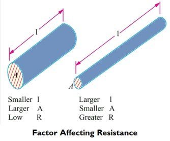
Cross-Section Area (a):- Another factor that affects resistance is the cross-sectional area of a material. The greater the cross-sectional area of a material, the lower the resistance. If two conductors have the same length but twice the cross-sectional area, there is twice as much current flow through the wire with the larger cross-sectional area.
Temperature:- Temperature also affects resistance. For most materials, the higher the temperature, the more resistance it offers to the flow of electric current. This effect is produced because a change in the temperature of a material changes the ease with which a material releases its outer electrons. A few materials, such as carbon, have lower resistance as the temperature increases. The effect of temperature on resistance varies with the type of material. The effect of temperature on resistance is the least important of the factors that affect resistance.
Factor effecting Impedance
The main factor that affects impedance is frequency. In AC circuits, capacitance and inductance can be important factors in determining the total impedance. Both capacitance and inductance are influenced by the frequency (cycles per second or hertz, Hz) at which the AC current reverses direction. The impedance is directly proportional to the frequency (f ) times the inductance and impedance is inversely proportional to the product of frequency and capacitor.
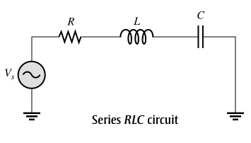
Effect of frequency in series Impedance
Consider the typical series RLC circuit the total reactance behaves as follows:
Starting at a very low frequency, XC is high, and XL is low, and the circuit is predominantly capacitive. As the frequency is increased, XC decreases and XL increases until a value is reached where XC = XL and the two reactances cancel, making the circuit purely resistive. As the frequency is increased further, XL becomes greater than XC and the circuit is predominantly inductive.
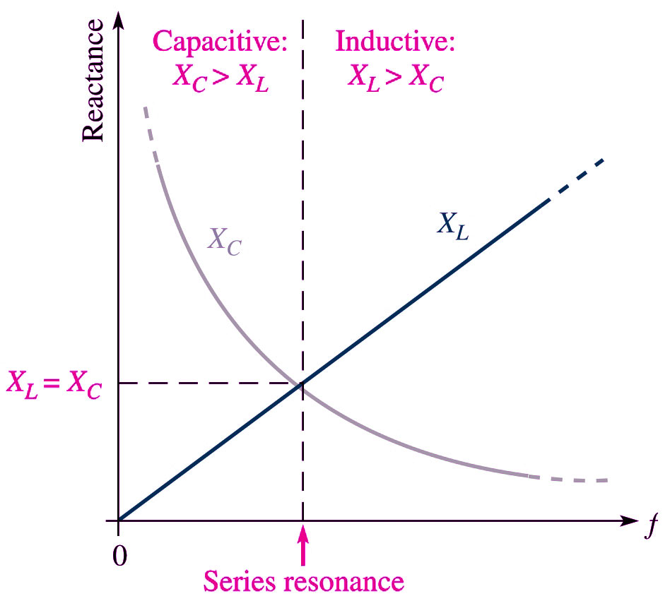
⇒ The circuit changed from capacitive to inductive as the frequency increased.
Note that with increase in the frequency the impedance magnitude decreased at first become minimum, equal to the resistance (resonance frequency) and then began increasing again.
Note:- Resistance doesn’t take into account the frequency of the signal passing through it, because frequency doesn’t affect the resistance of non-reactive components.
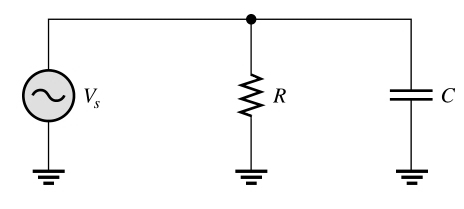
Effect of frequency in parallel Impedance
Ideally, the impedance of a parallel resonant circuit is infinite. In practice, the impedance is maximum at the resonant frequency and decreases at lower and higher frequencies, as indicated by the curve.
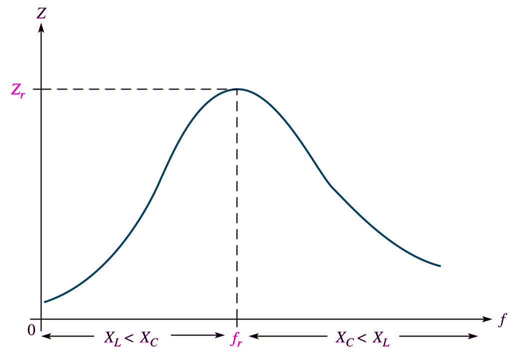
At very low frequencies, XL is very small and XC is very high, so the total impedance is essentially inductive. As the frequency increase, the impedance also increases, and the inductive reactance dominates until the resonant frequency is reached. As the frequency goes above resonance capacitive reactance dominate and the impedance decreases.
Note that with an increase in the frequency the impedance magnitude increases at first equal to the resistance (resonance frequency) and then began to decrease.
Application of Ohm’s law in resistance and impedance
Ohm’s law for Resistance
Ohm’s law states that the current flowing through a resistance is directly proportional to the potential difference between its ends and inversely proportional to the value of the resistance, provided the temperature remains constant. By applying Ohm’s law, the current flowing through a resistor can be calculated by measuring the voltage drop across it, provided the value of the resistance is known.
V = I × R
I = V/R
R = V/I
Ohm’s law for Impedance
The relationship between voltage, current, and impedance is defined by Ohm’s Law, which was derived by Ohm in the early nineteenth century. This law can be stated in three different but equivalent ways:
V = I × Z
I = V/Z
Z = V/I
Resistance vs Impedance Real and Imaginary Value
Resistance Real and Imaginary Value
Complex numbers are rarely used when dealing with direct current, but commonly used with alternating current. So the resistance only consists of the real value such as 10 ohms.
Impedance Real and Imaginary Value
In alternating current, the flow of electric charge periodically reverses direction. Because of this, many aspects of alternating current cannot be described with only one number. Real number ordered pairs could be used, but due to the sinusoidal nature of alternating current, there are advantages to using complex numbers.
Like all other complex numbers, any impedance has both a real and an imaginary part. The real part is termed the resistive component, and the imaginary part is termed the reactive component of the impedance. If we denote the resistive component by the variable R and the reactive component by the (real) variable X, impedance can be written as the sum:
Z = R ± jX
The current that flows in one direction is called direct current (DC). In alternating current (AC), the flow of charge reverses directions alternately every fraction of a second (every half-cycle). The cycle repeats over and over again.
Either or both of the terms in the sum may be zero. if R is positive in the above Equation the component absorbs power. That is, power flows from the circuit into the component and doesn’t come back again. Conversely, if R is negative, the component delivers power to the rest of the circuit (in this case, to the voltage source that it is connected to).
On the other hand, the X part of the impedance can be either positive or negative. A positive +jX is termed inductive because an ideal inductor’s reactance is +jX, where X is a positive (real) number. A negative −jX is termed capacitive for a similar reason. These are straightforward consequences of the fact that for sinusoidal excitation in an ideal inductor, the current waveform lags the voltage waveform (90°), and in an ideal capacitor, the current leads the voltage by 90°.
In brief, an impedance contain both imaginary and real parrts while one that is purely real (no imaginary part) is called resistance or “resistive impedance. Also all reactances are impedances, but not vice versa.
Power consumed in Impedance and Resistance
Electric power is consumed each time a voltage causes the current to flow. Power generally appears in the form of heat, light, or motion. The basic unit of measurement for electric power is the watt.
Power consumed in Resistance
In an electric circuit more power is taken from the supply than is fed back into it, since some power is dissipated by the resistance of the circuit, and therefore:
P = I2R (W)
In any d.c. circuit the power consumed is given by the product of the voltage and current, because in a d.c. circuit voltage and current are in phase.
Power consumed in Impedance
In an electrical circuit, energy is supplied by the source of emf, stored by the capacitive and inductive elements, and dissipated in resistive elements. Conservation of energy requires that, at any particular time, the rate at which energy is supplied by the source of emf must equal the rate at which it is stored in the capacitive and inductive elements plus the rate at which it is dissipated in the resistive elements. (We assume ideal capacitive and inductive elements that have no internal resistance.)
No power losses are associated with pure capacitors and pure inductors in an AC circuit. A pure capacitor, by definition, has no resistance or inductance, whereas a pure inductor has no resistance or capacitance.
In an impedance circuit when the current increases in one direction in an AC circuit, charge accumulates on the capacitor and a voltage drop appears across it.
This energy storage is only momentary, however: When the current reverses direction, the charge leaves the capacitor plates and returns to the voltage source.
During one-half of each cycle the capacitor is being charged, and during the other half the charge is being returned to the voltage source. Therefore, the average power supplied by the source is zero. In other words, no power losses occur in a capacitor in an AC circuit.
Similarly, the source most do work against the back emf of an inductor that is carrying a current. When the current reaches its maximum value, the energy stored in the inductor.
When the current begins to decrease in the circuit, this stored energy is returned to the source as the inductor attempts to maintain the current in the circuit. In an a.c. circuit the power consumed is given by the product of the current and that part of the voltage which is in phase with the current. The average power delivered to a resistor in an RLC circuit is given as
Pavg = ΔVrms. Irms. Cosφ
The average power delivered by the generator is converted to internal energy in the resistor. No power loss occurs in an ideal capacitor or inductor.
Power dissipation in Impedance and Resistance
Power dissipation in Resistance
In dc circuits the amount of power dissipated by the resistor is Real power or active power in the form of heat(I2R). This is because the dissipation of electrical energy in a resistor does not depend on the current’s direction. The power dissipation can be calculated by multiplying the voltage across a resistor by the current passing through it.
P = V.I watt
Power dissipation in Impedance
In ac circuits, there are three kinds of power: real, reactive, and apparent power. The kind of power that exists in purely resistive circuits is what is called real power or reactive power. In the impedance circuit, the electrical power is dissipated and stored.
Active power or Real Power:- It is the average of the instantaneous power over a time interval. It is the power consumed by the resistive loads in an electrical circuit. Real power is the power that is dissipated in the form of heat and is measured in watts
Preal = VI.Cosθ (watt)
Reactive power is the power consumed in an ac circuit because of the expansion and collapse of magnetic (inductive) and electrostatic (capacitive) fields. Unlike true power, reactive power is not useful power because it is stored in the circuit itself. This power is stored by inductors, because they expand and collapse their magnetic fields in an attempt to keep the current constant, and by capacitors because they charge and discharge in an attempt to keep the voltage constant.
The reactive power is the rate of energy flow between the source and the reactive components of the load (i.e., inductances and capacitances). It represents a lossless interchange between the load and the source.
PReactive = VI.sinθ Volt-ampere-reactive(VAR)
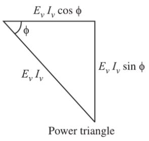
In an RLC circuit, there exists a combination of the magnitude of real power and reactive power. The phasor combination of resistive power ( true power ) and reactive power is called apparent power. Since the apparent power is a combination of real and reactive power, it cannot be designated either watts or VAR. Instead, it is measured in units called volt-amperes, abbreviated VA.
Apparent Power = Phasor sum of Real power + Reactive power
Papparent = VI Volt-ampere
Impedance and Resistance Physical Quantity: Scalar and Vector
Resistance Physical quantity
Resistance and reactance is a scalar quantity as it only has a magnitude. They can be added algebraically.
In a purely resistive circuit the total real power is the sum of all the individual real power values:
PR = PR1 + PR2 • • • + PRN
In a purely reactive circuit the total reactive power is the sum of all individual reactive power values:
PRE = PRE1 + PRE2 • • • + PREs
Impedance Physical quantity
Impedance is a Vector quantity consisting of both a magnitude Z and direction φ.
However, in Impedance circuits, the simple sum of the real power and reactive power does not equal the apparent power.
PT ≠ PR + PRE
This occurs because the phase relationship between the voltage across and the current through each component are different. Impedance is the vectorial sum of resistance and reactance.
The total apparent power is calculated using the Pythagoras theorem. It is equal to the square root of the real power squared plus the reactive power squared.
PT = √P2R + P2RE
Phase angle of Impedance and resistance
The phase difference, measured in degrees between the current and voltage, is called the phase angle of the circuit and is denoted by the symbol φ, the lower-case Greek letter phi.
Phase angle of resistance
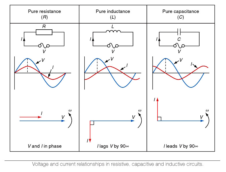
In an a.c. or d.c circuit containing resistance only, such as a heating circuit, the voltage and current are in phase, which means that they reach their peak and zero values together, as shown in Fig. Since the current and voltage are in the same phase, therefore, the phase angle of a purely resistive circuit is zero.
Phase angle of Impedance
When circuits contain two or more separate elements, such as RL, RC or RLC, the phase angle between the total voltage and total current will be neither 0° nor 90° but will be determined by the relative values of resistance and reactance in the circuit.
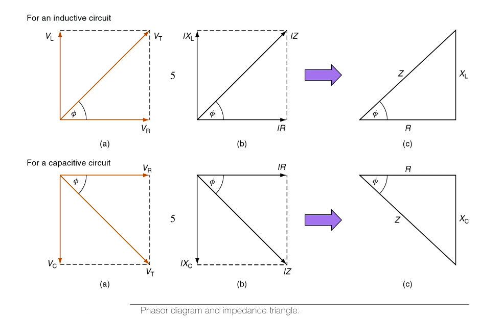
When a resistor only is connected to an a.c. circuit the current and voltage waveforms remain together, starting and finishing at the same time. We say that the waveforms are in phase. When a pure inductor is connected to an a.c. circuit the current lags behind the voltage waveform by an angle of 90°. We say that the current lags the voltage by 90°. When a pure capacitor is connected to an a.c. circuit the current leads the voltage by an angle of 90°.
In impedance circuits, the reactance can be either inductive or capacitive. In the series RLC circuit the current is the same through both elements, but with different voltages appearing across the resistance and reactance. In the parallel circuit, the same voltage is applied to both elements, but different currents may flow in the two branches. The phase relationship between current and voltage for the whole circuit can be anything between zero and ±90°. The phase angle depends on the relative amounts of resistance and reactance in the circuit.
Power factor of Resistance and Impedance
Power factor (P.F) is defined as the cosine of the phase angle between the current and voltage.
P.F = cosφ
The value of the power factor in a circuit, therefore, depends on the phase difference between the supply voltage and current.
Resistance Power factor
In a purely resistive circuit, the phase angle is zero, so the power factor is one.
P.F = Coso°
P.F = 1
Power factor of Impedance circuit
The ratio of the actual power of an alternating or pulsating current, as measured by a wattmeter to the apparent power, ae indicated by ammeter and voltmeter readings, The power factor of an inductor, capacitor, or insulator is an expression of their losses.
P.F = Cosφ = True power/Apparent Power
In a purely reactive circuit, the phase angle is 90°, so the power factor is zero. An inductive circuit has a lagging power factor (current lags voltage) a capacitive circuit has a leading power factor (current leads voltage) a resistive circuit has a power factor of one (unity power factor, as current and voltage are in phase).
A power factor of an impedance circuit can only range between 0 and 1, but can be either leading or lagging.
It’s usual to make voltage the reference, so a lagging power factor means the current is lagging the voltage.
Resistance and Impedance Measuring Instruments
Resistance Measurement
Resistance can be measured using an ohmmeter. An ohmmeter causes an electric current to flow through the device being measured to determine the resistance of the device. The battery in the ohmmeter is the voltage source for the current that flows through the device being measured. Unlike a voltmeter or ammeter, an ohmmeter is only used when there is no other voltage source in the circuit. Ohmmeters work best when measuring the resistance of a component that is completely isolated from the rest of the electrical system.
Impedance Measurement
The measuring of impedance means measuring its magnitude and the phase angle. At frequencies below 100MHz, the impedance magnitude can be determined by the voltage and current measurements. The phase difference between the voltage and current waveforms indicates whether the impedance is inductive or capacitive in nature. To specify the component values precisely, many measurements at several different frequencies are necessary. At high frequencies, such measurements become tedious, time-consuming, and lengthy. For such measurements, complex impedance measurement meters are used.
The impedance can be measured by two such tools
- Vector Impedance Meter
- RF vector impedance Meter
Summary Impedance vs Resistance
S.No |
Criteria |
Resistance |
Impedance |
1 |
Definition |
The opposition to the flow of DC or AC current caused by the nature and physical dimensions of a conductor. |
The total opposition offered to the flow of A.C current is called Impedance. |
2 |
Symbol |
Resistance is represented by “R” |
Impedance is represented by Z. |
3 |
SI unit |
Resistance is measured in Ohm. |
Impedance is measured in ohm. |
4 |
Factor affecting |
Resistance depends on length, cross-sectional area, temperature, and material. |
Impedance depends on the frequency of AC current. |
5 |
Circuit Component |
DC or AC circuit contains only resistive circuit (R) connected in series, parallel or series-parallel combinations. |
Impedance circuits consist of resistance, inductor, and capacitor connected in series, parallel or series-parallel combinations. |
6 |
Circuit Used |
Resistance can be used in both A.C and D.C circuit |
Impedance can be used in A.C circuit only. |
7 |
Effect of frequency |
Resistance is unaffected by frequency. It is independent of frequency variation. |
Impedance is always affected by the frequency variation due to inductive and capacitive components. |
8 |
Power consumed |
In a resistive circuit, only active power or real power is consumed. |
Impedance consumed both active and reactive power. In an Impedance circuit, the power consumed is given by the product of the current and that part of the voltage which is in phase with the current.Pavg = ΔVrms. Irms. Cosφ |
9 |
Power dissipation |
The power dissipated by the resistor is Real power or active power in the form of heat(I2R). |
In the impedance circuit, the electrical power is dissipated and stored. |
10 |
Real & complex value |
The resistance only consists of the real value such as 10 ohms. |
Impedance has both a real and an imaginary part. The real part is termed the resistive component, and the imaginary part is termed the reactive component of the impedance. |
11 |
Physical Quantity |
Resistance is a scalar quantity as it only has a magnitude. They can be added algebraically. |
Impedance is a Vector quantity consisting of both a magnitude Z and direction φ. |
12 |
Phase angle |
The current and voltage are in the same phase, therefore, the phase angle of a purely resistive circuit is zero. |
The phase relationship between current and voltage for the impedance circuit can be anything between zero and ±90°. |
13. |
Power factor |
The power factor of the resistance element is 1. |
The power factor of impedance is between 0 to 1 (leading or lagging). |
14. |
Measuring Instrument |
It can be measured by Ohm-meter. |
Impedance can be measured by
|