
1. Strain gauge is an example of which device?
A. Transducer
B. Voltage follower
C. Integrator
D. Differentiator
3. Transmission lines are used for
A. Output signal
B. Input signal
C. Signal transfer
D. All of the mentioned
4. The length of the transmission lines are
A. Longer than 10 meters
B. Shorter than 10 meters
C. Equals to 10 meters
D. None of the mentioned
5. Why output of the transducer is not directly connected to the indicator or display?
A. Low-level output is produced
B. High-level output is produced
C. No output is produced
D. Input is fed directly
6. What are the features of an instrumentation amplifier?
A. Low noise
B. High gain accuracy
C. Low thermal and time drift
D. All of the mentioned
7. What is the disadvantage of using LH0036 instrumentation op-amp?
A. Extremely stable
B. Relatively expensive
C. Accurate
D. All of the mentioned
Answer:b
LH0036 is a very precise special-purpose circuit in which most electrical parameters are minimized and performance is optimized. So, it is relatively expensive.
8. What instrument is used to amplify the output signal of the transducer
A. Peaking amplifier
B. Instrumentation amplifier
C. Differential amplifier
D. Bridge amplifier
9. General purpose op-amps are used in applications as
A. Instrumentation amplifier
B. Differential instrumentation amplifier
C. Inverting instrumentation amplifier
D. Non-inverting instrumentation amplifier
10. In an instrumentation amplifier using a transducer bridge, which device measures the change in physical energy
A. Resistive transducer
B. Indicating meter
C. Capacitive transducer
D. Inductor circuit
11. The temperature of a thermistor increases, when the value of its resistance
A. Remain constant
B. Increase
C. Decrease
D. Depends on the heating material
12. Consider the entire resistors in the bridge circuit are equal. The resistance and change in resistance are given as 3kΩ and 30kΩ. Calculate the output voltage of the differential instrumentation amplifier?
A. 4.95v
B. 1.65v
C. 8.25v
D. 14.85v
13. Consider a thermistor having the following specifications: RF=150kΩ at a reference temperature of 35oC and temperature coefficient of resistance = 25oC. Determine the change in resistance at 100oC.
A. -1.625MΩ
B. 9.75MΩ
C. 4.78MΩ
D. None of the mentioned
14. Consider the given bridge circuit, and find the voltage across the output terminal, Vab.
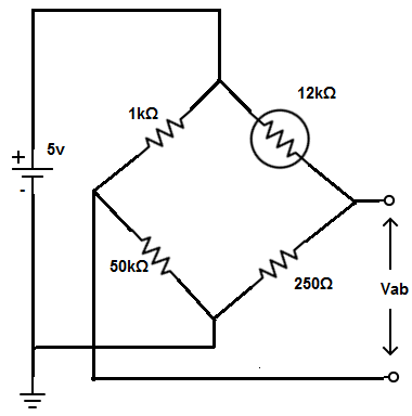
A. Vab = 4.9v
B. Vab = -5.6v
C. Vab =1.2v
D. Vab =-8.2v
15. Express the equation for the transducer bridge, if all the resistor values are equal
A. v=-(△R×Vdc)/(2×R+△R)
B. v=-(△R×Vdc)/2×(R+△R)
C. v=-Vdc/[2×(2×R+△R)].
D. v=-(△R×Vdc)/ [2×(2×R+△R)].