1. In alternating current circuits, the instantaneous power _____
Varies Continuously
Remain Stationary
Varies for a Fixed amount of Time
Any of the above
Answer.1. Varies Continuously
Explanation:
In alternating current circuits, the instantaneous power varies continuously as the voltage and current vary while going through a cycle. In such a case, the power at any instant is given by
P(t) = V(t) × I(t)
where p(t), v(t), and i(t) are values of instantaneous power, voltage, and current
2. An electric iron designed for 110 V AC supply was rated at 500 W. It was put across a 220 V supply. Assuming that at 110 V it supplied 500 W output (i.e. no losses) at the new voltage it will supply
2500 W
250 W
500 W
2000 W
Answer.4. 2000 W
Explanation:
Given
V = 110 V
P = 500 W
R = V2/P = (110)2/500 = 24.2Ω
Now new voltage:
V = 220 V since R = 24.2 Ω
P = V2/R = (220)2/24.2
P = 2000 Watt
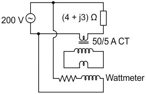
3. In a wattmeter the voltage across the pressure coil is 200 ∠0° V and load impedance is 4 +j3 = 5∠36.87°. If the current flows through the current coil is 50/5 A. Then the average power consumed by the wattmeter is
640 W
320 W
800 W
400 W
Answer.1. 640 W
Explanation:
Given,
Vpc = V = 200 ∠0° V
Z = Impedance = 4 +j3 = 5∠36.87°
I= Current from supply = V/Z = 200∠0°/5∠36.87° = 40∠-36.87°A
Icc = 40 × (5/50) = 4. A
ϕ = 36.87°
From concept
Average power = 200 × 4 × cos 36.87° = 640 W
4. Which method can be used to measure the power in a three-phase unbalanced load system?
One wattmeter method
Two wattmeter method
Three voltmeter method
Three ammeter method
Answer.2. Two wattmeter method
Explanation:
The ‘Two-wattmeter’ method is one of the most commonly used methods of measuring the power of a three-phase load.. In accordance with Blondel’s Theorem, this method will work for both balanced and unbalanced loads providing there are only three conductors supplying the load.
The ‘Two-Wattmeter Method’, has the following advantages:
It works for both star- and delta-connected loads.
It works for both balanced and unbalanced loads.
For balanced loads, the results can be used to determine the load’s power factor.
Note:- The simplest method of measuring the total power of a balanced or an unbalanced, three-phase three- or four-wire, the system is to use the ‘’Three-Wattmeter Method”.
5. In a circuit, voltage and current are given by V = 10 sin(ωt – 30°), i = 10 sin (ωt + 30) calculate the power consume in this circuit:
6. The power delivered to a single-phase inductive load is measured with a dynamometer type wattmeter using a potential transformer (PT) of turns ratio 200:1 and the current transformer (CT) of turns ratio 1:5. Assume both the transformers to be ideal. The power factor of the load is 0.8. If the wattmeter reading is 200 W, then the apparent power of the load in kVA is ______.
300 kVA
200 kVA
250 kVA
150 kVA
Answer.4. 150 kVA
Explanation:
Given that, potential transformer turns ratio = 200 : 1
8. The simplest and most common method of reducing any ‘effect of inductive coupling’ between measurement and power circuits is achieved by using
A screen around the entire measurement circuit
Twisted pairs of cable
Capacitor(s) to be connected at the power circuit
Capacitor(s) to be connected at the measurement circuit
Answer.2. Twisted pairs of cable
Explanation:
Inductive coupling results from time-varying magnetic fields generated by currents in nearby noise circuits. These magnetic fields, through mutual inductance with signal circuits.
Twisted pairs of cables are the most commonly and the simplest method of reducing the ‘effect of Inductive coupling’. (can be reduced to zero)
Methods to reduce the effect of Inductive coupling:
Limit the length of wire running in parallel.
Decrease the cable height
Whenever possible place the cable near the metal surface.
Use twisted cables.
Shield of cables on high frequencies ground the shield at two-point and on low frequencies at a single point.
Use optical Insulation.
Can be reduced by using the channel and grounded metal bones.
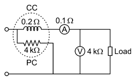
9. While measuring power observed by the load using the arrangement shown in the figure, the obtained values voltmeter and ammeter readings are 150 V and 12 A respectively. If the load power factor is unity, the wattmeter reading will be
1800 W
1756.8 W
1824.2 W
1843.2 W
Answer.4. 1843.2 W
Explanation:
Given that
Current through current coil (I) = ammeter reading = 12 A.
Power factor = cos ϕ = 1
Resistance of current coil = Rcc = 0.2 Ω
Ammeter resistance = RA = 0.1 Ω
The pressure coil voltage = The voltage drop across the current coil and ammeter + voltmeter reading.
V = I (Rcc + RA) + 150
V = 12 (0.2 + 0.1) + 150
∴ V= 153. 6 V
Watt meter reading is
W = VI cos ϕ
= (153.6) (12) (1)
∴ W = 1843.2 W
10. The compensating coil of a _______ compensates for the effect of the impedance of the voltage coil circuit.
High power Factor Wattmeter
Low power factor Wattmeter
Dynamometer
Ammeter
Answer.2. Low power factor Wattmeter
Explanation:
The compensating coil of a low power factor wattmeter compensates the effect of the impedance of the voltage coil circuit.
For low power factor circuits, the connection may result in very large errors. Due to the low power factor, the value of the current in the circuit is high while the power to be measured is small making the power loss considerably large. Thus, for low power factor wattmeters, the compensation of pressure coil current is mandatory.
Compensation for pressure coil inductance: Large errors are caused by pressure coil inductance in low power factor circuits. To compensate for these errors, a capacitance is connected in parallel to a part of the series resistance of the pressure coil circuit.