1. Wattmeter cannot be designed on the principle of
Electrostatic instrument
Thermocouple instrument
Moving iron instrument
Electrodynamic instrument
Answer.3. Moving iron instrument
Explanation:
We can use electrostatic instruments to measure voltage and power. These types of wattmeters are used for the measurement of a small amount of power, practically when the voltage is high and the power factor is low. It is also used for measurement of dielectric loss of cables on alternating voltage and for calibration of wattmeter and energy meters.
Thermocouple instruments are used to measure current, voltage, and power.
We can use the moving iron instrument to measure current and voltage only.
Electrodynamic instruments are the most preferred instruments for measurement.
2. Two wattmeter method is used for the measurement of power in a balanced three-phase load supplied from a balanced three-phase system. If one of the wattmeters reads half of the other (both positive), then the power factor of the load is
3. A single-phase load is connected between R and Y terminal of a 415 V, symmetrical, 3 – phase, 4 – wire system with phase sequence RYB. Load resistance of 100 Ohms is connected in a wattmeter. The power factor of the load is 0.8 lagging. The wattmeter will read.
4. A 300 V, 5 A, LPF wattmeter has a full scale of 300 W. The wattmeter can be used for loads supplied by 300 V AC mains with a maximum power factor of ________
0.2
0.5
0.8
0.1
Answer.1. 0.2
Explanation:
Power measured by 1- ϕ wattmeter is given by P = VpcIcc cos ϕ
Where
Vpc = Voltage of potential coil
Icc = Current through the current coil
Here, Vpc = 300 V , Icc = 5 A , P = 300 W (Full Scale)
300 = Vpc Icc cos ϕ
300 = 300 × 5 cos ϕ
cos ϕ = 0.2
5. Statement (I): The reactive power of the three-phase balanced load can be measured with the use of a single wattmeter.
Statement (II): For measurement of reactive power the current coil is connected to one of the phases of a 3-ϕ network.
Both Statement (I) and Statement (II) are individually true and Statement (II) is the correct explanation of Statement (I).
Both Statement (I) and Statement (II) are individually true, but Statement (II) is not the correct explanation of Statement (I).
Statement (I) is true, but Statement (II) is false.
Statement (I) is false, but Statement (II) is true.
Answer.2.
Explanation:
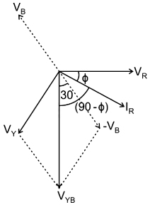
The power measured by the wattmeter is given by
W = IRVYBcos(IRVYB)
From the phasor diagram, we can observe that the phase angle between IR and VYB is 90 – ϕ.
⇒ W = VYBIR cos (90 – ϕ)
⇒ W = VLIL sin ϕ
⇒ W = √3 VphIph sin ϕ
But we know that three-phase reactive power Q = 3 VphIph sin ϕ
So, so by multiplying the wattmeter reading by √3 we can get three-phase reactive power.
Q (total) = √3 W = 3-ϕ reactive power
For the measurement of reactive power, the current coil is connected to one of the phases of a 3-ϕ network.
And the potential coil is to be connected between the remaining two phases.
6. In case of power measurements by two wattmeter method in a balanced 3-phase system with pure inductive load
Both wattmeters will indicate the same value but with opposite signs
Both wattmeters will indicate zero
Both the wattmeters will indicate the same value same sign
One wattmeter will indicate zero and the other will indicate the same non-zero value.
Answer.1. Both wattmeters will indicate the same value but with opposite signs
Explanation:
Given that load is pure inductive – Hence it is zero power factor (lag)
Cos ϕ = 0
⇒ ϕ = 90°
The reading of two wattmeters can be expressed as
W1 = VLILcos(30 + φ) W2 = VLILcos(30 − φ)
When P.F reads zero (φ = 90°)
Such a case occurs when the load consists of pure inductance or pure capacitance
In this condition, the two wattmeter reads equal and opposite i.e W1 + W2 = 0
W1 = -W2
7. A 3-phase star-connected load is supplied with 440 V and 50 Hz supply, two wattmeter method is used to measure the power in the load. The readings of the wattmeter are 2000 W and – 1000 W. What is the value of the capacitor in μF to be connected in series with each phase of load such that the power is measured by one wattmeter.
8. The apparent power drawn by an AC system is 50 kVA, reading of the wattmeter is 20 kW. Reactive power consumed will be
45.82 kVAR
50 kVAR
70 kVAR
20 kVAR
Answer.1. 45.82 kVAR
Explanation:
Given that,
Apparent power (S) = 50 kVA
Reading of wattmeter = Active power (P) = 20 kW
Apparent Power
$S = \sqrt {{P^2} + {Q^2}}$
$ \Rightarrow 50 = \sqrt {{{20}^2} + {Q^2}}$
Q = 45.82 kVAR
9. In a particular test, the readings of two wattmeters are 5 kW and 1 kW. If the second-meter connections are reversed, the total power and power factor are
10. Two wattmeters are connected to measure the power consumed by a 3-ϕ load with a power factor of 0.4. The total power consumed by the load as indicated by the two wattmeters is 30 kW. The difference between the two wattmeter readings is _____ kW.
40.44 kW
35.59 kW
39.69 kW
42.25 kW
Answer.3. 39.69 kW
Explanation:
P = 30 W, cos ϕ = 0.4
If P1 and P2 are two individual wattmeter readings then according to the problem,
11. A 3-phase 500 V motor load has a power factor of 0.5. Two wattmeters are connected to measure the input. They show the input to be 36 kW. The readings of both the instruments are.