61. The main Drawback of Dual-beam oscilloscope is
Large size
Heavy-weight
Uneven Brightness
All of the above
Answer.4. All of the above
Explanation:
The dual-beam oscilloscope can generate the two-electron beams within the cathode ray tube either by using a double electron gun tube or by splitting beam. In this method, the brightness and focus of each beam are controlled separately. But two tubes increase the size and weight of the oscilloscope and it looks bulky.
Nowadays, double beam oscilloscope is outdated, as this function could be performed by the digital scope with greater efficiency and they do not require a dual-beam display. The digital scope captures a single beam of electrons and simultaneously splits into many channels.
In dual or double Beam Oscilloscope the two displays may have noticeably different brightness if operated at widely spaced sweep speeds. The brightness and focus control also affects the two traces at the same time.
62. In a multi-beam oscilloscope __________
Single beam is produced
Three beams are produced
Many beams are produced
Two beams are produced
Answer.3. Many beams are produced
Explanation:
Multiple beam oscilloscope has a single tube but several beam producing systems inside. Each system has a separate vertical deflecting pair of plates and generally a common time base system. The triggering can be done internally using either of the multiple inputs or externally by an external signal or line voltages.
63. The main difference between a dual-beam oscilloscope as compared to the dual-trace oscilloscope is
Two different Electron gun is used
Signals are displayed simultaneously
Signal must have sam frequency
All of the above
Answer.4. All of the above
Explanation:
Difference between Dual Beam and Dual Trace Oscilloscope
The dual-beam oscilloscope has two different electron gun which passes through two completely separate vertical channels, whereas a dual-trace oscilloscope has a single electron beam that gets split into two and passes through two separate channels.
Dual Trace
Dual Beam
One electron beam and one vertical amplifier are used to generate two traces.
Two electron beams and two vertical amplifiers are used.
Two signals are not displayed simultaneously in real-time but appear to be displayed simultaneously.
The two signals are displayed simultaneously.
A single beam is used to share between the two signals hence difficult to switch quickly between the traces.
Two beams are used hence easy to switch between the traces.
Two signals have different frequencies.
Two signals must have the same frequency or their frequencies must be integer multiple of each other.
Cannot operate at fast speeds because the two separate fast transient signals cannot be done.
It can operate at a very fast speed.
The cost is low due to the single beam.
The cost is more due to two beams.
Size and weight are less.
Size and weight are more as compared to dual trace oscilloscope.
64. How many generators are used in the Delayed time base oscillators?
4
2
6
1
Answer.2. 2
Explanation:
A delayed time base oscilloscope has two base generators, a normal time base, and an additional delayed time base, which is superimposed on the normal time base output.
This facility allows any portion of a displayed waveform to be brightened when the oscilloscope is operating on a normal time base.
65. In delay time base oscilloscope switching to delayed time base causes
Decrease screen brightness
Increase screen Brightness
Completely fill the screen
Partially fill the screen
Answer.3. Completely fill the screen
Explanation:
In delay time base oscilloscope switching to delayed time base causes the brightened portion to completely fill the screen for detailed investigation.
66. In delay time base oscilloscope, the input signal of the vertical plates is delayed for
Infinite Time
Finite-time
10 Sec
1 Minute
Answer.2. Finite-time
Explanation:
In delay time base oscilloscope the input signal of the vertical plates is delayed by some finite time with delay circuit. The signal before the delay circuit is applied to the trigger time base circuit to the horizontal section. This allows the study of all leading or lagging edges of a pulse-type waveform.
67. The additional time base generator in the delay time base oscilloscope is superimposed on
Normal Time base Generator
Normal Time base Generator Output
Voltage Comparator
Additional time base Generator output
Answer.4. Additional time base Generator output
Explanation:
The delayed time base oscilloscope uses two-time base generators. One is a normal time base while the other one is an additional time base generator. The additional time base generator is superimposed on the additional time base generator output. Due to this additional time base, the waveform can be brightened when the oscilloscope is running on a normal time base.
68. In Delay time base oscilloscope ______ base circuit is used for main time base circuits.
Normal time base
Delay time base
Summing circuit
Deflection circuit
Answer.4. Additional time base Generator output
Explanation:
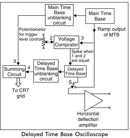
In Delay time base oscilloscope the normal time base circuit is used for main time base circuits which works the same as in other oscilloscopes.
The main time base unblanking circuit produces an unblanking pulse which is applied to CRT grid to turn on an electron beam in the CRT during the sweep time.
The ramp output of the main time base is applied to the vertical comparator and to the horizontal deflection amplifier through the switch.
The other input to the voltage comparator is derived from the potentiometer whose level is adjustable.
69. The ramp output of the main time base is applied to the _______ in the Delayed time base oscilloscope.
Main time base Unblanking circuit
Voltage Comparator
Horizontal amplifier
Both 2 and 3
Answer.4. Both 2 and 3
Explanation:
In Delay time base oscilloscope the normal time base circuit is used for main time base circuits which works the same as in other oscilloscopes.
The main time base unblanking circuit produces an unblanking pulse which is applied to CRT grid to turn on an electron beam in the CRT during the sweep time.
The ramp output of the main time base is applied to the vertical comparator and to the horizontal deflection amplifier through the switch.
The other input to the voltage comparator is derived from the potentiometer whose level is adjustable.
When the levels of ramp output of the main time base and trigger level set by potentiometer are equal then the voltage comparator produces a negative or positive output spike at that instant.
This spike triggers the delayed time base circuit.
The main time base and delayed time base unblanking circuit produces an unblanking pulse during the ramp time of the delayed time base. The unblanking pulse from these is applied to the summing circuit and then applied to the CRT.
70. When the levels of ramp output of the main time base and trigger level are equal then the voltage comparator produces ______
Negative spike Only
Positive spike Only
Both negative and Positive spike
None of the above
Answer.4. Both 2 and 3
Explanation:
In Delay time base oscilloscope the normal time base circuit is used for main time base circuits which works the same as in other oscilloscopes.
The main time base unblanking circuit produces an unblanking pulse which is applied to CRT grid to turn on an electron beam in the CRT during the sweep time.
The ramp output of the main time base is applied to the vertical comparator and to the horizontal deflection amplifier through the switch.
The other input to the voltage comparator is derived from the potentiometer whose level is adjustable.
When the levels of ramp output of the main time base and trigger level set by potentiometer are equal then the voltage comparator produces a negative or positive output spike at that instant.
This spike triggers the delayed time base circuit.
The main time base and delayed time base unblanking circuit produces an unblanking pulse during the ramp time of the delayed time base. The unblanking pulse from these is applied to the summing circuit and then applied to the CRT.