1. Which one of the following is a passive element/source to an electrical circuit?
Current source
Voltage source
Resistor
Battery
Answer.3. Resistor
Explanation
The resistor is a passive element of an electrical circuit. While current source, voltage source, and battery are all active elements.
Active and passive components form the two main types of electronic circuit elements.
An active component supplies energy to an electric circuit and hence has the ability to electrically control the flow of charge.
A passive component can only receive energy, which it can either dissipate or absorb.
2. ______ is a basic network element that supplies power to the networks.
Resistor
Source
Inductor
Capacitor
Answer.2. Source
Explanation:-
The source is a basic network element that supplies power to the networks.
An electrical source is a device that is capable of converting nonelectric energy to electric energy and vice versa.
A discharging battery converts chemical energy to electric energy, whereas a battery being charged converts electric energy to chemical energy.
A dynamo is a machine that converts mechanical energy to electric energy and vice versa. If operating in the mechanical-to-electric mode, it is called a generator.
The important thing to remember about these sources is that they can either deliver or absorb electric power, generally maintaining either voltage or current.
3. Which of the following is not the Ideal Electric source?
Ideal Charging Source
Ideal Current Source
Ideal voltage Source
Both 2 & 3
Answer.1. Ideal Charging source
Explanation
The two sources of electrical energy are the voltage source and the current source. These sources may be classified as ideal or nonideal, dependent or independent.
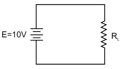
Ideal Voltage source:- An ideal voltage source (also called constant voltage source) is one that maintains a constant terminal voltage no matter how much current is drawn from it.
Fig. shows an ideal voltage source of 10 V. Regardless of the values of load resistance R, the terminal voltage will remain 10 V. An ideal voltage source has zero or negligible internal resistance that there is a negligible voltage drop in the internal resistance due to change in current. Consequently, the terminal voltage remains constant.
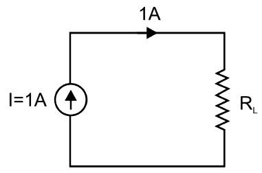
Ideal current source: An ideal current source (also called constant current source) is one that will supply the same current to any resistance connected across its terminals.
Fig. shows an ideal current source of 1A. Regardless of the value of load resistance R, the source will supply of 1A. The schematic symbol for a current source is a circle with an arrow in it. The arrow shows the direction of the current (conventional) produced by the source.
4. An ideal voltage source is connected across a variable resistance. The variation of current as a function of resistance is given by
A straight line passing through the origin
A rectangular hyperbola
A parabola
It could be any one of the above
Answer.2. A rectangular hyperbola
Explanation:-
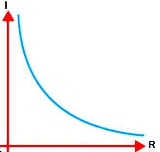
According to Ohm’s law V = IR
For a fixed source value of V,
we have I ∝ 1/R
Hence the graph of I versus R is a rectangular hyperbola as shown in the figure.
5. The dependent sources are of ________ kinds.
5
2
3
4
Answer.4. 4
Explanation
Each dependent source consists of two parts: the controlling part and the controlled part.
The controlling part is either an open circuit or a short circuit.
The controlled part is either a voltage source or a current source.
There are four types of dependent sources that correspond to the four ways of choosing a controlling part and a controlled part.
These four dependent sources are called the voltage-controlled voltage source (VCVS), a current-controlled voltage source (CCVS), voltage-controlled current source (VCCS), and current-controlled current source (CCCS).
6. The terminal voltage of an ideal DC voltage source is 12 V when connected to a 2 W resistive load. When the load is disconnected, the terminal voltage rises to 12.4V. What are the values of source voltage, Vs, and internal resistance Rs of the source?
4.2 ohm
2.4 ohm
3.6 ohm
2 ohm
Answer.2. 2.4 ohms
Explanation:-
When the load is disconnected i.e. open-circuited, the terminal voltage is 12.4 V. Therefore, the source voltage is 12.4
And, when the resistive load of 2 W, the terminal voltage seen is 12 V.
Therefore internal resistance Rs
Voc − Vs = I × Rs
P = V.I
2 = 12 × I
I = 1/6A
12.4 − 12 = Rs/6
Rs = 2.4 Ω
7. Which of the following electrical source has Internal resistance?
The real voltage and current source have internal resistance. Let’s discuss in detail
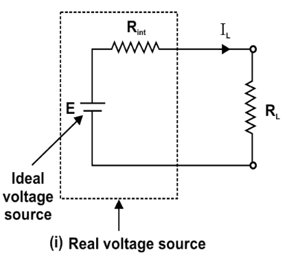
The real (non-ideal) voltage source has internal resistance that causes its terminal voltage to decrease when current is drawn from it.
A real source can be represented as an ideal voltage source in series with a resistance equal to its internal resistance (Rint ) as shown in Fig. This representation can be used to calculate the true terminal voltage of a voltage source when the current is drawn from it. Note that internal resistance is an inherent property of a source, it is not a discrete component that can be measured with an ohmmeter. As (Rint ) becomes small, the voltage source more closely approaches the ideal voltage source.
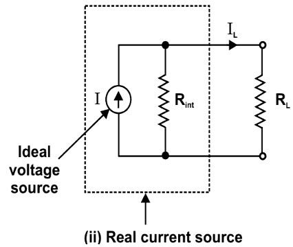
A real current source can be represented as an ideal current source in parallel with an internal resistance (Rint) as shown in Fig.
When load resistance R, is connected across the terminals, the current (I) produced by the source divides between (Rint), and RL. Consequently, the load current is less than it would be in case the source was ideal. Note that an ideal current source would have infinite internal resistance (i.e. (Rint) would be replaced by an open circuit).
In that case, all the source current would be delivered to the load. As the shunt resistance R, becomes greater, the current source approaches the ideal current source more closely.
8. The internal resistance of an ideal voltage source is
0
Infinite
1 Ω
Can’t say
Answer.1. 0
Explanation:-
An ideal voltage source has zero or negligible internal resistance that there is a negligible voltage drop in the internal resistance due to change in current. Consequently, the terminal voltage remains constant.
9. The internal resistance of an ideal current source is
0
Infinite
1 Ω
Can’t say
Answer.2. Infinite
Explanation:-
An ideal current source (also called constant current source) is one that will supply the same current to any resistance connected across its terminals.
The internal resistance is the ratio of change of voltage across the device to the change in current through it, we see that the internal resistance must be infinitely large. The voltage across the source changes but the current, in an ideal source, does not. Hence the change in the current is zero, and any number, when divided by zero, gives an infinitely large quotient.
10. A practical current source is usually represented by
Resistance in series with an ideal current source
Resistance in parallel with an ideal current source
Resistance in series with an ideal voltage source
Resistance in parallel with an ideal voltage source
Answer.2. Resistance in parallel with an ideal current source
Explanation:-
A real current source can be represented as an ideal current source in parallel with an internal resistance (Rint) as shown in Fig.
When load resistance R, is connected across the terminals, the current (I) produced by the source divides between (Rint), and RL. Consequently, the load current is less than it would be in case the source was ideal. Note that an ideal current source would have infinite internal resistance (i.e. (Rint) would be replaced by an open circuit).
In that case, all the source current would be delivered to the load. As the shunt resistance R, becomes greater, the current source approaches the ideal current source more closely.
11. A practical voltage source is usually represented by
Resistance in series with an ideal current source
Resistance in parallel with an ideal current source
Resistance in series with an ideal voltage source
Resistance in parallel with an ideal voltage source
Answer.3. Resistance in series with an ideal voltage source
Explanation:-
The real (non-ideal) voltage source has internal resistance that causes its terminal voltage to decrease when current is drawn from it.
A real source can be represented as an ideal voltage source in series with a resistance equal to its internal resistance (Rint ) as shown in Fig. This representation can be used to calculate the true terminal voltage of a voltage source when the current is drawn from it. Note that internal resistance is an inherent property of a source, it is not a discrete component that can be measured with an ohmmeter. As (Rint ) becomes small, the voltage source more closely approaches the ideal voltage source.
12. In CCVS, voltage depends on the control current and the constant called _______
Transconductance
Transresistance
Current Gain
Voltage Gain
Answer.2. Transresistance
Explanation:-
Current-controlled voltage source (CCVS):- The controlled source of electric energy, whose output voltage depends on the control current (input current) and does not depend on the load current.
In CCVS, voltage is directly proportional to the control current. The constant of proportionality is called Transresistance(r).
13. In CCCS, current depends on the control voltage and the constant called _______
Transconductance
Transresistance
Current Gain
Voltage Gain
Answer.1. Transconductance
Explanation:-
Current-controlled current source (CCCS):- The controlled source of electric energy, whose output current depends on the control current (input current) and does not depend on the load voltage.
I2 = gmV1
The current I, depends only on the voltage V1 and the constant gm is called the transconductance or mutual conductance.
14. Which of the following is not an example of a linear element?
Resistor
Thermistor
Inductor
Capacitor
Answer.2. Thermistor
Explanation
Ideally, resistors, capacitors, inductors, voltage sources, and current sources are linear circuit elements. If you graph the current vs. voltage characteristic for a linear component you get a straight line.
A non-linear equation is such which does not form a straight line. It looks like a curve in a graph and has a variable slope value. An example of a non-linear element is a diode, thermocouple, thermistor, etc.
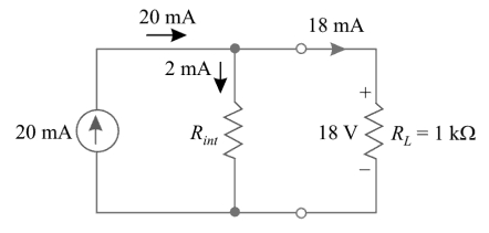
15. When a 1 kΩ load is connected across a 20 mA current source, it is found that only 18 mA flows in the load. What is the internal resistance of the source?
10 Ω
18 Ω
9 Ω
20 Ω
Answer.3. 9Ω
Explanation
The fig for given problem is shown below
Load Voltage VL = RL× IL
= 18 mA × 1 KΩ = 18 V
Internal resistance current Int = 20 − 18 = 2mA
Since Rint is parallel with RL, voltage Rint is same as VL i.e 18 V