Ques.11. For thyristor pulse triggering is preferred to D.C triggering because:
- Gate dissipation is low
- Pulse system is simpler
- Triggering signal is required for short duration
- All of the above
Answer.4. All of the above Explanation:- Pulse Triggering:- A positive pulse of energy can be used to trigger an SCR into conduction instead of a continuous form of ac or DC. Triggering by this method takes advantage of the latching characteristic of an SCR. When conduction is initiated, it can be made continuous for the remainder of the alternation. The duration of the triggering pulse may be extremely short. This method of triggering, in general, consumes very little energy from the source. The operational efficiency of a pulse-triggered SCR is usually much higher than that of other gate-triggering methods. D.C gate triggering: In this method, a dc voltage of proper magnitude and polarity is applied between the gate and the cathode in such a way that the gate is positive with respect to the cathode. When the applied voltage is sufficient to produce the necessary gate current, the SCR switches on. Since the power circuit (anode-cathode circuit) is also D.C there is no isolation between the power circuit and the triggering circuit. This method requires a continuous D.C signal which causes more gate power loss. Advantages of Pulse Triggering over D.C gate triggering Thyristors and triacs can be triggered by a single pulse, a train of pulses or a steady d.c. voltage on the gate. Pulse triggering is most frequently used; single-pulse triggering is used in specific applications and low-cost systems, and d.c. triggering only in cases of difficulty in reaching latching current. A thyristor or triac with the anode positive with respect to the cathode, and with adequate gate drive, will turn on within 10μs. Conduction will continue irrespective of load current for as long as the gate drive is present. Conduction will continue after the gate drive ceases only if the load current has reached the latching level. Pulse triggering is preferred to d.c. triggering for general use because the gate dissipation is lower and the trigger system is simpler. Both pulse and d.c. trigger systems must be synchronized to the mains supply, and both use a pulse generator operating through a variable delay to provide control over the trigger angle required for phase control. Whereas in a pulse trigger system the output from the pulse generator can be passed to the thyristor gate through an isolating transformer, a d.c. trigger system requires either rectification of the pulse transformer output or gating of a further supply by the pulse transformer to provide the d.c. gate drive. A simple trigger circuit for thyristors and triacs can be constructed with a diac. The diac is a three-layer device and therefore, strictly speaking, not a thyristor. Its function, however, is as a trigger device for thyristors, and it is generally considered with these devices.
Ques.12. Which gate has a low output, only when both the input is high?
- NOR
- OR
- NAND
- AND
Answer.3. NAND
Explanation:-
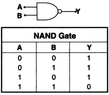
NAND gate: This function behaves like an AND gate followed by an inverter (hence the NAND, which means NOT AND). It produces a low output only if all of its inputs are high. If any input is low, the output is high.
Ques.13. The electric switches are put in the
- Live wire
- Earth wire
- Neutral wire
- Any of these
Answer.1. Live wire Explanation:- Switches are used to turn an electric appliance on and off. It works as a manually controlled protective device. For interruption of the flow of current. In case of an accident where someone touches the live wire and get an electric shock, a switch can be used as a safety device to cut off the current. It should be noted that all the switches are put in the live wire, so that when we switch off an electrical appliance (like an electric iron), then its connection with the live wire is cut off and there will be no danger of an electric shock if we touch the metal case of the electrical appliance. If, however, if we put switches in the neutral wire, then the live wire will be in connection with the electrical appliance ever when the switch is in the off position, and there is a danger of an electric shock.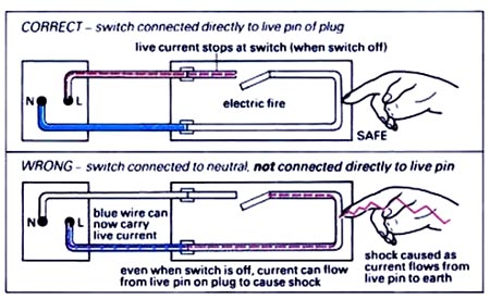
Ques.14. In TIG welding, the welding zone is shielded by an atmosphere of
- Hydrogen gas
- Oxygen gas
- Either 1 & 2
- Helium gas
Answer.4. Helium gas Explanation:- Tungsten Inert Gas Arc Welding (TIG). In the tungsten inert gas arc welding process, the arc is established between the tungsten electrode and the parent metal. The electrode is mounted centrally on a nozzle-shaped hood through which an inert gas is passed as shown in Fig. The inert gases used are helium or argon. Filler metal if required is fed separately. Generally direct current of the order of 500 to 950 amperes is used for most thicknesses. It is a very quick process as it employs a continuous wire filler metal. No electrode coating is required due to shielding by inert gases. This process is specially used for welding light alloys and non-ferrous materials like aluminum, copper, and magnesium. Welds produced by TIG welding are strong, ductile, free from distortion, and corrosion-resistant.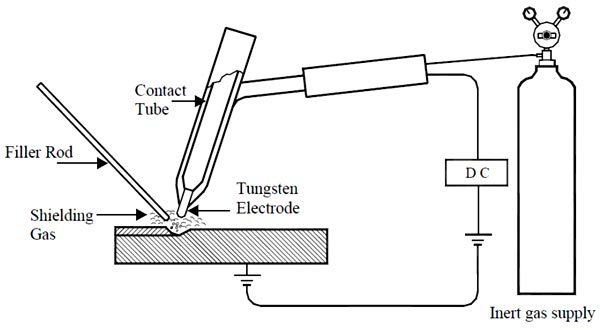
Ques.15. The capacity of the battery is given in terms of:-
- Ampere-Hour
- Voltage
- Weight of the battery
- Volume of the electrolyte
Answer.1. Ampere-Hour Explanation:- The amount of energy that a battery can store is caged by its capacitor. A water tank, for example, with a capacity of 8000 liters can hold at most 8000 liters. Similarly, a battery can only store a fixed amount of electrical energy, typically marked on the side of the battery by the manufacturer. Actually battery capacity is measured in the amount of charge it can hold. Now we know the current is charge per unit time, therefore the product of current and time gives us the charge. That is why battery capacities are measured in milliampere-hour in the case of cellphone batteries or ampere-hour in the case of automotive batteries. Battery capacity = charge stored = current x time or amp-hr. The capacity of a battery is measured in amp-hours (Ah). This indicates the amount of energy that can be drawn from the battery before it is completely discharged A battery of 100 Ah should ideally give a current of 2 amps for 50 hours (i.e. 2 amps times 50 hours equals 100 amperes).
Ques.16. The turbine suitable for low heads and high flow rates is:-
- Pelton Wheel
- Francis
- Kaplan
- All of these
Answer.3. Kaplan Explanation:- Based on the head of the water level, the hydraulic turbine is classified as low head, medium head, and high head turbine. Low head turbines: These turbines work under low heads ranging between 3 and 50 m of water. They are designed for higher discharge rates E.g. Kaplan Turbine. Medium head turbines: These turbines work under medium heads ranging between 55 and 400 m. They are designed for medium discharge rates E.g. Francis Turbine. High head turbines: These turbines are designed only for low discharges and work under high heads ranging above 300-400 m.E.g Pelton Turbine.
Ques.17. Power loss in a resistor is given by:
- P = V2R
- P = V2/R
- P = I2/R
- P = V/I
Answer.2. P= V2/R Explanation:- The power loss in the resistor is given by P = V2/R or P = I2R
Ques.18. The path of magnetic flux in a transformer should have:
- High resistance
- High Reluctance
- Low resistance
- Low Reluctance
Answer.4. Low Reluctance Explanation:-
Ques.19. Which of the following transistor configurations gives useful current gain?
- CE alone
- CB alone
- CC alone
- Both CE and CC
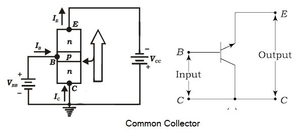
Answer.4. Both CE and CC Explanation:- Common Emitter In this circuit, the emitter terminal is common to both the input i. e. base-emitter circuit, and the output i.e. the collector-emitter circuit and is grounded. The input (or emitter) circuit is forward biased by connecting the positive of the emitter-base battery VBB to the emitter terminal and the output (or collector) circuit is reverse biased by connecting the negative of the collector-emitter battery VCC to the collector terminal. So, output resistance is more than input resistance. High current gain In a common emitter connection, Ic is the output current and IB is the input current. The collector current here is expressed as: Ic = βIB + ICEO As the value of β is very large, therefore, the output current IC is much more than the input current IB. This increases the current gain effectively. The current gain of CE arrangement ranges from 20 to High Voltage and Power Gain As we have seen above, CE arrangement has a high current gain. This in turn increases the voltage and power gain of the CE circuit. In comparison to CB and CC circuits, the common emitter connection has the highest voltage and power gain. For this reason, the CE transistor connection is often used for amplifying purposes. Common-Collector Configuration In a common-collector configuration, the collector terminal of a transistor is connected as a common terminal between input and output as shown in fig. The base and collector terminals are used to apply the input signal whereas the output signal is obtained. The CC configuration is also commonly known as the emitter follower or the voltage follower. This is because the output signal across the emitter is almost the replica of the input signal with little loss. In other words, the output voltage follows the input voltage and hence the voltage gain will be a maximum of one. The common-collector configuration is used primarily for impedance-matching purposes since it has a high input impedance and low output impedance, opposite to that of the common-base and common-emitter configuration. Common Collector Current gain- γ or Γ The current gain beta (y) is defined for the common-emitter configuration of a BJT and can be defined in two forms: The dc current amplification factor (γdc) and the ac current amplification factor (γac). The dc current gain γdc is defined as the ratio of emitter current to base current under dc biasing conditions. ${\gamma _{dc}} = \dfrac{{{I_E}}}{{{I_B}}}$ For practical devices, the value of Atypically ranges from about 50 to over 400 (one greater than β) Similarly, the ac current gain Yac is defined as the ratio of change in emitter current to a corresponding change in base current at a given VCE under ac signal conditions ${\gamma _{ac}} = \dfrac{{{I_E}}}{{{I_B}}}$ A common-collector configuration offers the following characteristics. The characteristics are similar to that for the CE configuration. Note:- For common base configuration current amplification factor is α For common emitter configuration, the current amplification factor is β [ninja_tables id=27501]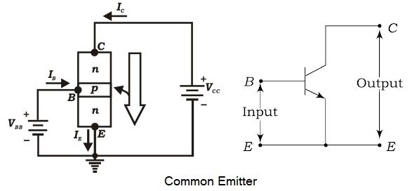
Where β = Current Gain
ICEO = Collector-Emitter current
500.
Ques.20. The resistance can be measured most accurately by
- Bridge method
- Megger
- Multimeter
- Voltmeter-ammeter method
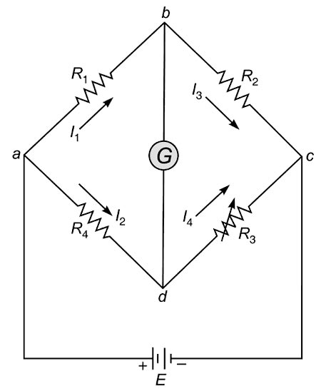
Answer.1. Bridge method Explanation:- A bridge circuit in its simplest form consists of a network of four resistance arms forming a closed circuit, with a dc source of current applied to two opposite junctions and a current detector connected to the other two junctions, as shown in Fig. The bridge is said to be balanced when there is no current flow through the galvanometer or when the potential difference across the galvanometer is zero. To have zero current through the galvanometer, the points “B” and “D” must be at the same potential. Thus potential across arm “AB” must be the same as the potential across arm “AC”. The Wheatstone bridge circuit is used to compare an unknown resistance with a known resistance. Bridge circuits are extensively used for measuring component values such as R. L and C. Since the bridge circuit merely compares the value of an unknown component with that of an accurately known component (a standard), its measurement accuracy can be very high. This is because the readout of this comparison is based on the null indication at bridge balance, and is essentially independent of the calibration of indicating instrument. The measurement accuracy is therefore directly related to the accuracy of the bridge component and not to that of the indicator used. The basic dc bridge is used for accurate measurement of resistance and is called Wheatstone’s bridge.