
11. How should a fuse be installed in a circuit to ensure proper operation?
- Parallel to the load
- Series with the load
- Either way possible
- At the ground point
Answer.2. Series with load
Explanation:-
Fuse is the current interrupting device that breaks or opens the circuit (in which it is inserted) by fusing the elements when the current in the circuit exceeds a certain value.
Fuse is the simplest and cheapest device used for interrupting an electrical circuit under the condition of short-circuiting, or excessive overload, current magnitudes.
A fuse is a safety device having a short length of a thin, tin-plated copper wire having a low melting point, which melts and breaks the circuit if the current exceeds a safe value. The thickness and length of the fuse wire depend on the maximum current allowed through the circuit. An electric fuse works on the heating effect of current. The fuse for protecting our domestic wiring is fitted just above our main switch on the switchboard. A fuse wire is connected in series in the electric circuits so that current flowing through the conductor to any load must also pass through the fuse.
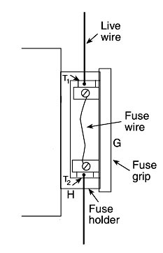
The main fuse in domestic wiring consists of a porcelain fuse holder H having two brass terminals T1 and T2 in it. This is connected in the live wire. The other part of the fuse is a removable fuse grip G which is also made of porcelain. The fuse grip has a fuse wire fixed in it. When fuse grip is inserted in the fuse holder as shown in Figure, then the circuit of our domestic wiring is completed. So, under normal circumstances when the current is within the limit, then the fuse wire is intact and electric current is available in our wiring.
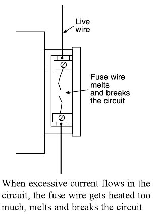
When a short circuit takes place, or when overloading takes place, the current becomes large and her the fuse wire too much. Since the melting point of fuse, wire is much lower than copper wires, the fuse wire melts and breaks the circuit as shown in Figure. When the fuse wire breaks, electricity supply automatically switched off before any damage can be done to the rest of the wiring (or the electric appliances being used).
We will now give some important points about the fuse wire to be used in electrical circuits. First of all, we should know why we use a thin wire as a fuse wire and not a thick wire. We use a thin wire in a fuse because it has a much greater resistance than the rest of connecting wires. Due to its high resistance, the heating effect of current will be much more in the fuse wire than anywhere else in the circuit. This will melt the fuse wire whereas other wirings will remain safe. We should not use a thick wire as a fuse wire because it will have low resistance and hence it will not get heated to its melting point easily. The fuse wire is usually made from tin-plated copper wire having a low melting point so that it may melt easily. A pure copper wire cannot be used as a fuse wire because it has a high melting point due to which it will not be easily when a short circuit takes place.
Fuse wire is made with an alloy of lead and tin having the low melting point and low resistance (although the resistance of fuse wire is higher than that of electrical appliances). If due to any malfunction or fault, excessive current begins to flow through the circuit, the fuse wire immediately melts due to the heat generated by the flowing current. The circuit is broken and the excess current, which may damage equipment is prevented from flowing.
It is used for Overload and for short-circuit protection in high voltage (upto 66 kV) and for low Voltage (upto 120 V – 240 V) installations/circuits.
Characteristics of a fuse are:-
- It should have a low melting point.
- It should have low ohmic losses.
- It should have high conductivity. ( or low resistivity)
- It should be economical.
- It should be free from detraction.
12. Which type of insulation covering the conductor is used for low voltages?
- Poly-vinyl Chloride(P.V.C)
- Paper
- Vulcanised Indian Rubber
- Cotton and silk Insulation
Answer.4. Cotton and silk insulation
Explanation:-
Insulating Materials:- The various insulating materials used in cables are as follows:
Silk and Cotton:– These types of insulation materials are used on conductors which are used for low voltage purposes. These insulated wires are usually used for instrument and motor winding.
Polyvinyl Chloride (PVC):- It is a synthetic compound material and comes as a white odorless, tasteless, chemically inert, non-inflammable, and insoluble powder. It is combined chemically with a plastic compound and is wed over the conductor as an insulation cover. PVC has the good dielectric strength and a dielectric constant of 5. Its maximum continuous temperature rating is 75° C. It is inert to oxygen and almost chemically stable, so it is preferred over VIR cable &. PVC insulated cables are usually employed for medium and low voltage domestic, industrial lights, and power installations.
Vulcanized India Rubber (VIR) it is useful for low-voltage power distribution systems only, because of its small size. It is prepared by mixing India rubber with mineral matter such as sulfur, zinc oxide, red lead, etc. It has a reasonable value of dielectric strength (15 kV/mm). Its use is limited because of its low melting point, low chemical resistance capability and short span of life. The advantage of using vulcanized India rubber is that when it is used for a cable, the cable becomes stronger and more durable. It can withstand high temperatures and remain more elastic than pure rubber. The drawback of using this material for insulation is that it attacks copper. Hence, before using VIR as insulation, the copper conductor must be tinned well.
Impregnated Paper:- This is used as an insulator in case of power cables because it has low capacitance, high dielectric strength (30 kV/mm), and is economical. The paper is manufactured with wood pulp, rags or plant fiber by a suitable chemical process. It has high resistance due to high resistivity under dry condition. The drawback of this cable is that it absorbs a small amount of moisture only, which reduces the insulation resistance. Therefore, a paper insulated cable always requires some sort of protective covering and it is impregnated in insulating oil before use.
13. In places where acids and alkalies are present, the type of wiring used is
- PVC
- TRS
- VIR
- Weather Proof
Answer.1. PVC
Explanation:-
PVC wiring
In the field of insulated cables, PVC cables have occupied an important place and in fact, these are most popularly used in homes for domestic wiring. Various types of PVC cables are available, e.g., cables for control, signaling, instrumentation, rural electrification and house wiring, communication as well as for use in wires, automobiles, T.V. electric welding etc. These cables are suitable where the wire-temperature during use does not exceed 70°C. Polyvinyl chloride (PVC) cables are used for low and medium voltage distribution system. They are usually of two grades viz., 250/440 volts grade cable and 640 ⁄ 1100 volts grade cable. The conductors used in these cables are also of stranded aluminum or copper wires which are separately insulated with PVC insulation.
Wiring with PVC sheathed cables is installed directly under exposed conditions of sun and rain or in damp places. This system of wiring is suitable in situations where acids and alkalis are likely to be present. Where attack from white ants (termite) is prevalent, anti-termite treatment should be given. In cases where there are chances of any damage to the wirings, they should be covered with sheet metal protective covering. The base of the covering is made flush with the plaster or brickwork.
PVC cables are more flexible, non-draining, and.have the following properties.
- High mechanical strength
- High resistance to abrasion
- High fire resistance at high temperature
- High resistance to acid, oil and chemical fumes
- High dielectric strength and high insulation resistance even when dipped in water
- High aging property
- High corrosion resistance and can be laid directly underground in places where the soil is of active nature
14. Replacement of wiring is not easy in which type of wiring
- Conduit System
- Lead sheathed
- Concealed wiring
- Cleat System
Answer.3. Concealed wiring
Explanation:-
Concealed conduit wiring: in this method, the conduits are buried under the wall at the time of plastering. This is also called recessed conduit wiring.
The beauty of the premises is maintained due to conduit wiring. It is durable and has a long life lt protects the wires from mechanical shocks and fire hazards. Proper earthing of conduits makes the method electrical shock-proof. It requires very little maintenance.
The repairs are very difficult in the case of concealed conduit wiring. This method ~ most costly and erection requires highly skilled labor. These are a few disadvantages of the conduit type of wiring. In concealed conduit wiring, keeping conduit at earth potential is necessary.
Advantages of Conduit Wiring Systems
- It is the safest wiring system (Concealed conduit wring)
- Appearance is very beautiful (in case of concealed conduit wiring)
- No risk of mechanical wear & tear and fire in case of metallic pipes.
- Customization can be easily done according to future needs.
- Repairing and maintenance are easy.
- There is no risk of damage to the cable’s insulation.
- it is safe from corrosion (in case of PVC conduit) and risk of fire.
- It can be used even in humidity, chemical effect, and smoky areas.
- No risk of electric shock (In case of proper earthing and grounding of metallic pipes).
- It is a reliable and popular wiring system.
- sustainable and long-lasting wiring system.
Disadvantages of Conduit Wiring Systems
- It is an expensive wiring system (Due to PVC and Metallic pipes, Additional earthing for metallic pipes Tee(s) and elbows, etc.
- Very hard to find defects in the wiring.
- installation is not easy and simple.
- Risk of Electric shock (In case of metallic pipes without proper earthing system)
- Very complicated to manage additional connections in the future.
15. The minimum aluminum conductor of size ________ is used for a subcircuit in domestic wiring.
- 1/1.8 mm
- 1/1.24 mm
- 1/1.4 mm
- 1/1.2 mm
Answer.3. 1/1.4 mm
Explanation:-
It is essential to determine the conductor size. It should also be known whether a copper or aluminum conductor is to be used. The sizes and prices of copper and aluminum conductors largely differ. The points to be considered while calculating the size of the conductor are current carrying capacity, voltage drop in conductor and minimum permissible size of the conductor.
The current carrying capacity of a circuit depends on the total connected load. Thus, knowing the total load connected to the circuit, the conductor should be selected as per IS codes.
The minimum size of the conductor in the sub-circuit should not be less than 1/8 in the case of copper wires and 1/1.4 mm (1.5 mm2) in the case of aluminum wires.
16. As per IE rules, the permissible variation voltage at the consumer end is
- ± 6%
- ± 10%
- ± 12%
- ± 2%
Answer.1. ± 6%
According to Indian Electricity Rules, the permissible voltage drop from the supply terminal to any point on the wiring system should not exceed ±6% volt of the nominal supply voltage.
17. Highly skilled labor is required in
- TRS wiring
- Conduit wiring
- Casing-capping wiring
- Both conduit and casing-capping wiring
Answer.4. Both conduit and casing-capping wiring
The type of labor required for different wiring systems is:
| S.No | Wiring System | Type of labor Required |
| 1 | Cleat wiring | Semiskilled/Low skilled |
| 2 | Casing capping wiring | Highly skilled |
| 3 | CTS/TRS wiring | Skilled |
| 4 | Lead sheathed wiring | Skilled |
| 5. | Metal conduit winding | Highly skilled |
| 6 | PVC conduit wiring | Skilled |
18. Which of the following types of wiring preferred for workshop lighting?
- Casing Capping
- Batten wiring
- Concealed conduit wiring
- Surface conduit wiring
Answer.4. Surface conduit wiring
If the conduit wiring, steel tubes are installed on the surface of walls by means of pipe hooks (surface conduit wiring)
Surface conduit wiring is best suitable for workshops, Industries, laboratories. because in concealed wiring system alternation of light-position after full setup is virtually impossible.
19. Supplier’s fuse, which is provided in domestic wiring system is
- After the energy meter
- Before the energy meter
- Before Distribution board
- After the main switch
Answer.1. After the energy meter
Just after the supply, the consumer must provide the main switch which would control the complete lighting and power circuit of the house. This switch operates simultaneously on the live phase and neutral. The fuse unit box is generally sealed by supplier and the consumer does not have the authority to replace or repair the fuse. In case of blowing out, the authorized person appointed by the electric supply company is only permitted to replace the blown-out fuse.
20. The acceptable value of grounding resistance to the domestic application is
- 0.1Ω
- 1Ω
- 10Ω
- 100 Ω
Answer.1. 0.1Ω
Earth resistance should be as small as possible. It depends on the voltage level of the system to be grounded. As the voltage level increases the earth’s resistance is required to be nearer to zero as far as possible. The NFPA and IEEE recommend a ground resistance value of 5 ohms or less.
For domestic application, the earth resistance should be between 0.2 – 0.5 ohms
