Ques.21. The acceleration rate of trains on suburban services is
- 0.1 to 0.4 km phps
- 1 to 6.5 km phps
- 10 to 26 km phps
- 0.8 to 1 km phps
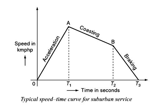
Answer.2. 1 to 6.5 km phps Explanation:- In suburban service, the distance between two adjacent stops for an electric train is lying between 1 and 8 km. In this service, the distance between stops is more than the urban service and smaller than the mainline service. The typical speed—time curve for suburban service is shown in Fig. The speed-time curve for urban service consists of three distinct periods they are: (i) Acceleration. (ii) Coasting. (iii) Retardation. For this service, there is no free-running period. The coasting period is comparatively longer since the distance between two stops is more. The braking or retardation period is comparatively small. It requires relatively high values of acceleration and retardation. Typical acceleration and retardation values are Iying between 1.5 and 5 kmph and 3 and 4 kmph, respectively.The speed-time curve for suburban service
Ques.22. The motor used in electric traction is
- Synchronous Motor
- 3 phase induction motor
- DC Shunt Motor
- Single-phase induction motor
Answer.2. 3 phase induction motor Explanation:- For electric traction, DC series motors are best suited. DC series motors and AC series motors are very much recommended, as they provide a high starting torque Nowadays three-phase induction motors are also being used.
Ques.23. A composite system consists of
- A combination of diesel engine and dc series motor
- A combination of diesel engine and AC single phase motor
- Single-phase power received is converted into dc or three-phase power ac system
- Use of combination of dc and ac motors on the same locomotive
Answer.3. Single-phase power received is converted into dc or three-phase power ac system Explanation:- Composite System Such a system incorporates the good points of two systems while ignoring their bad points. 1-φ AC system is preferable in view of distribution cost and distribution voltage can be stepped up to high voltage with the use of transformers, which reduces the transmission losses. Whereas in DC system, DC series motors have the most desirable features and for the 3-φ system, 3-φ induction motor has the advantage of automatic regenerative braking, So, it is necessary to combine the advantages of the DC/AC and 3-φ/1-φ systems. The above cause leads to the evolution of the composite system.
Ques.24. The specific energy consumption for suburban services is usually
- 18 to 25 watt-hours per tonne-km
- 50 to 75 watt-hours per tonne-km
- 125 to 150 watt-hours per tonne-km
- 155 to 200 watt-hours per tonne-km
Answer.2. 50 to 75 watt-hours per tonne-km Explanation:- The energy input to the motors is called energy consumption. This is the energy consumed by various parts of the train for its propulsion. The energy drawn from the distribution system should be equal to the energy consumed by the various parts of the train and the quantity of energy required for lighting, heating, control, and braking. This quantity of energy consumed by the various parts of the train per ton per kilometer is known as specific energy consumption. It is expressed in watt-hours per ton per km. Specific energy consumption = Total energy consumed in Wh ⁄ train mass in tonne × run length in km The specific energy consumption is inversely proportional to the distance between stations. The greater the distance between stops is, the Lesser will be the specific energy consumption The typical values of the specific energy consumption is less for the mainline service of 20-30 W-hr/ton-km and high for the urban and suburban services of 50-70 W-hr/ton-km.
Ques.25. Single-phase to three-phase system in electric traction is also called as
- Kando System
- Synchronous System
- Diesel System
- Steam System
Answer.1. Kando System Explanation:- Single-phase to the 3-φ system or kando system In this system, 1-φ AC system is preferred for the distribution network. Since single-phase overhead distribution system is cheap and 3-φ induction motors are employed as traction motor because of their simple, robust construction, and the provision of automatic regenerative braking. The voltage used for the distribution network is about 15-25 kV at 50 Hz. This 1-φ supply is converted to 3-φ supply through the help of the phase converters and the high voltage is stepped down transformers to feed the 3-φ induction motors Frequency converters are also employed to get high-starting torque and to achieve better speed control with the variable supply frequency. By using silicon controlled rectifier as an inverter, it is possible to get variable-frequency 3-phase supply at 1/2 to 9 Hz frequency. At this low frequency, 3-phase motors develop high starting torque without taking excessive current. The advantages of this system include higher starting efficiency, less number of substations, simple substation design and lower cost of fixed installations.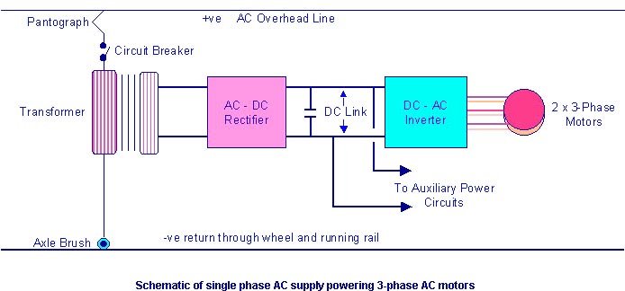
Ques.26. The speed of locomotive is controlled by
- Gearbox
- Flywheel
- Regulating steam flow to the engine
- Applying brakes
Answer.3. Regulating steam flow to the engine Explanation:- Prior to 1788, the speed of the steam engine was manually controlled. The worker read speed on the indicator and increased or decreased the steam flow by setting steam flow valve. The process of manual control could be divided into two steps: 1. Observe the current speed, and then compare the actual speed and the desired speed 2. Set steam flow valve according to the speed error E. (I) If E is positive (which means the actual speed is lower than the desired), set the flow valve to increase the steam flow rate; the aim is to increase the actual speed. (II) If E is negative (which means the actual speed is higher than the desired), the steam flow rate should be reduced. The earliest significant work in modern automatic control can be traced to James Watt’s design of the fly-ball governor (1788) for the speed control of a steam engine. This device served to keep the speed of the engine at a selectable level regardless of the load by controlling the volume of steam available to the piston during each revolution. There is the combustion chamber where the fuel is burned, producing steam in the boiler, which through its pressure and expansion drives the crank and slider mechanism that turns the wheels. There is also a Watt’s governors as shown in Fig. The engine speed was monitored by the “lift” of rotating balls that worked against a spring. The initial tension of the spring was the reference, which was determined by the desired speed. As the rotating balls rose or fell, the steam control valve closed or opened via mechanical linkage in such a sense as to compensate for the speed change. Obviously, the automatic control process was similar to that of manual control. However, the difference in an automatic control process was that the observing, comparing, and setting (for the automatic control process) were performed by the controller automatically. Hence, an important conclusion that could be drawn is that the automatic control process, in fact, includes measuring errors of the controlled variables and correcting or diminishing them automatically (according to the errors). This device opens or closes the steam supply according to the actual wheel speed, too fast and the steam supply is throttled, too slow and the steam supply is opened up. It ensures that the locomotive runs at a nearly constant speed.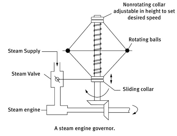
Ques.27. When the speed of the train is estimated taking into account the time of stop at a station in addition to the actual running time between stops, is known as
- Average speed
- Schedule speed
- Notching speed
- Free running speed
Answer.2. Schedule speed Explanation:- Schedule speed The ratio of the distance covered between two stops to the total time of the run including the time for the stop is known as schedule speed. It is denoted with the symbol Vs. Schedule speed = Distance between Stops ⁄ Total time of run + Time of Stop
Ques.28. For supply on 25 kV, 50 Hz single phase, the suitable motor for electric traction is
- Ac single-phase split phase motor
- Ac single phase universal motor
- Dc shunt motor
- Dc series motor
Answer.4. DC series motor Explanation:- The single phase 25 kV, 50 Hz railway became a global standard because of rectifier locomotives with DC motors. Without them, HVDC railway would have remained the standard and might have evolved into a 6000 V DC. railway25 kV alternating current electrification is commonly used in railway electrification systems worldwide, especially for high-speed rail. The advantage here is the use of the main 50 Hz grid systems instead of special low-frequency traction generating stations. Although 50 Hz AC commutator motors were feasible but it requires a large number of poles and brushes to limit the internal losses. It was possible to use AC motors (and some railways did, with varying success), but they have less than ideal characteristics for traction purposes. This is because control of speed is difficult without varying the frequency and reliance on voltage to control speed gives a torque at any given speed that is not ideal. This is why DC series motors are the best choice for traction purposes, as they can be controlled by voltage, and have an almost ideal torque vs speed characteristic. When taking traction power from industrial frequency supplies, d.c. series motors are preferred, fed through a rectifier, using a variable voltage from a tap changer (for rectifiers), or from a fixed-voltage winding on the main transformer (in thyristor control). This dc supply is finally fed to D.C series traction motor fitted between the wheels. The system of traction employing 25-kV, 50-Hz, 1-phase ac supply has been adopted for all future track electrification in India.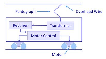
Ques.29. Power supply frequency for 25 kV single phase system is
- 161
- 25
- 50
- 60
Answer.3. 50 Hz Explanation:- The power supply frequency for 25 kV single-phase AC system is 50 Hz in INDIA. In countries where 60 Hz is the normal grid power frequency, 25 kV at 60 Hz is used for the railway electrification.
Ques.30. The coasting retardation on city service is approximately
- 0.16 km phps
- 1.6 km phps
- 16 km phps
- 25 km phps
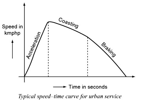
Answer.1. 0.16 km phps Explanation:- Coasting Period:- During the Coasting period, the Power to the motors is cut off at the point so that the train runs under its momentum, the speed gradually falling due to friction, windage etc. During this period, retardation remains practically constant. Coasting is desirable because it utilizes some of the kinetic energy of the train which would, otherwise, be wasted during braking. Hence, it helps to reduce the energy consumption of the train. Speed-time curve for urban or city service The speed—time curve urban or city service is almost similar to suburban service and is shown in Fig. In this service also, there is no free-running period. The distance between two stop is less about 1 km. Hence, relatively short coasting and the longer braking period is required. The relative values of acceleration and retardation are high to achieve a moderately high average between the stops. Here, the small coasting period is included to save the energy consumption. The acceleration for the urban service lies between 1.6 and 4 kmph. The coasting retardation is about 0.15 kmph and the braking retardation is lying between 3 and 5 kmph. Note:- Free running and costing periods are generally long in case of Mainline service