121. Which circuit can be used to take the square root of a signal?
A. Divider circuit
B. Multiplier circuit
C. Squarer circuit
D. None of the mentioned
Answer: A
A divider circuit can be used to find square roots by connecting both the inputs of the multiplier (in the divider) to the output of an op-amp.
122. Find the output voltage of the squarer circuit?
A. Vo = √( Vref/|Vin|)
B. Vo = √( Vref×|Vin|)
C. Vo = √( Vref2×|Vin|)
D. Vo = √( Vref×|Vin|2)
Answer: B
The output of the square root circuit is proportional to the square root of the magnitude of the input voltage.
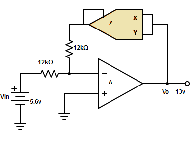
123. Find the current, IL flowing in the circuit given below
A. IL = 1.777mA
B. IL = 1.048mA
C. IL = 1.871mA
D. None of the mentioned
Answer: D
Voltage, VL = Vo2/ Vref =132/10 = 16.9v.
∴ IL = VL/R = 16.9/12kΩ = 1.408mA.
124. A square root circuit built from the multiplier is given an input voltage of 11.5v. Find its corresponding output voltage?
A. 11v
B. 15v
C. 13v
D. Cannot be determined
Answer: D
The input voltage must be negative or else the op-amp will saturate and lie between the ranges of -1 to -10v.
125. The circuit in which the output voltage waveform is the integral of the input voltage waveform is called
A. Integrator
B. Differentiator
C. Phase shift oscillator
D. Square wave generator
Answer: A
The integrator circuit produces the output voltage waveform as the integral of the input voltage waveform.
126. Find the output voltage of the integrator
A. Vo = (1/R×CF)×t∫0 Vindt+C
B. Vo = (R/CF)×t∫0 Vindt+C
C. Vo = (CF/R)×t∫0 Vindt+C
D. Vo = (R×CF)×t∫0 Vindt+C
Answer: A
The output voltage is directly proportional to the negative integral of the input voltage and inversely proportional to the time constant RCF.
Vo = (1/R×CF)×t∫0 Vindt+C
Where C-> Integration constant and CF-> Feedback capacitor.
127. Why an integrator cannot be made using a low pass RC circuit?
A. It requires a large value of R and a small value of C
B. It requires a large value of C and a small value of R
C. It requires a large value of R and C
D. It requires a small value of R and C
Answer: C
A simple low pass RC circuit can work as an integrator when the time constant is very large, which requires the large value of R and C. Due to practical limitations, the R and C cannot be made infinitely large.
128. How a perfect integration is achieved in op-amp?
A. Infinite gain
B. Low input impedance
C. Low output impedance
D. High CMRR
Answer: A
In an op-amp integrator, the effective input capacitance becomes CF×(1-Av). Where Av is the gain of op-amp. The gain is infinite for the ideal op-amp. So, the effective time constant of the op-amp integrator becomes very large which results in perfect integration.
129. The op-amp operating in open-loop results in the output of the amplifier saturating at a voltage
A. Close to op-amp positive power supply
B. Close to op-amp negative power supply
C. Close to op-amp positive or negative power supply
D. None of the mentioned
Answer: C
In practice, the output of the op-amp never becomes infinite rather the output of the op-amp saturates at a voltage close to the op-amp’s positive or negative power supply depending on the polarity of the input dc signal.
130. The frequency at which gain is 0db for the integrator is
A. f=1/(2πRFCF)
B. f=1/(2πR1CF)
C. f=1/(2πR1R1)
D. f=(1/2π)×(RF/R1)
Answer: B
The frequency at which the gain of the integrator becomes zero is f=1/(2πR1CF).
131. Why practical integrator is called a lossy integrator?
A. Dissipation power
B. Provide stabilization
C. Changes input
D. None of the mentioned
Answer: D
To avoid saturation problems, the feedback capacitor is shunted by a feedback resistance(RF). The parallel combination of RF and CF behaves like a practical capacitor that dissipates power. For this reason, the practical integrator is called a lossy integrator.
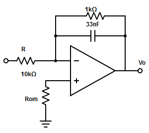
132. Determine the lower frequency limit of integration for the circuit given below.
A. 43.43kHz
B. 4.82kHz
C. 429.9kHz
D. 4.6MHz
Answer: B
The lower frequency limit of integration,
f= 1/(2πRFCF)
= 1/(2π×1kΩ×33nF)
= 4.82kHz.
133. Find the range of frequency between which the circuit act as an integrator?
A. [1/(2πRFCF)]– (2πR1CF)
B. (2πRFCF) – [1/(2πR1CF)].
C. [1/(2πRFCF)]- [1/(2πR1CF)].
D. None of the mentioned
Answer: C
The range of frequency between which the circuit act as an integrator as
[1/(2πRFCF)]- [1/(2πR1CF)].
134. What will be the output voltage waveform for the circuit, R1×CF=1s and input is a step voltage. Assume that the op-amp is initially nulled.
A. Triangular function
B. Unit step function
C. Ramp function
D. Square function
Answer: C
Input voltage Vin = 1.2v for 0≤t≤0.4ms. The output voltage at t=0.4ms is
Therefore, the output voltage waveform is a ramp function.
135. Find R1 and RF in the lossy integrator so that the peak gain and the gain down from its peak is 40db to 6db. Assume ω=20,000 rad/s and capacitance = 0.47µF.
A. R1 = 10.6Ω, RF = 106Ω
B. R1 = 21.2Ω, RF = 212.6Ω
C. R1 = 42.4Ω, RF = 424Ω
D. R1 = 29.8Ω, RF = 298Ω
Answer: B
The gain of the lossy integration is
A=(RF/ R1)/√[1+(ωRFCF)]2
=> A(dB. = 20log{(RF/R1)/√[1+(ωRFCF)]2}
=> 40db = 20log×[(RF/R1)/√1
=> R1 = RF/20.
At ω=20000rad/s, the gain is down by 6db from its peak of 20db and thus is 14db.
136. Why a resistor is shunted across the feedback capacitor in the practical integrator?
A. To reduce the operating frequency
B. To enhance low-frequency gain
C. To enhance error voltage
D. To reduce error voltage
Answer: D
The input current charging the feedback capacitor produces error voltage at the output of the integrator. Therefore, to reduce error voltages a resistor (RF) is connected across the feedback capacitor. Hence, RF minimizes the variation in the output voltage.
137. Find the application in which integrator is used?
A. All of the mentioned
B. Analog Computers
C. FM Detectors
D. AM detectors
Answer: B
The integrator is most commonly used in analog computers mainly for signal waveshaping.
138. At what condition the input signal of the integrator is integrated properly
A. T = RFCF
B. T ≤ RFCF
C. T ≥ RFCF
D. T ≠ RFCF
Answer: C
The input signal will be integrated properly if the time period T of the signal is larger than or equal to RF×CF (Feedback resistor and capacitor).
139. What happens if the input frequency is kept lower than the frequency at which the gain is zero?
A. Circuit acts like a perfect integrator
B. Circuit acts like an inverting amplifier
C. Circuit acts like a voltage follower
D. Circuit acts like a differentiator
Answer: B
If the input frequency is lower than the lower frequency limit of the integrator (i.e. when gain = 0), there will be no integration results and the circuit act as a simple inverting amplifier.
140. Match the correct frequency range for integration. (Where f –> Input frequency and fa –> Lower frequency limit of integration)
1. f a
i. Results in 50% accuracy in integration
2.f = fa
ii. Results in 99% accuracy in integration
3.f = 10fa
iii. No integration results
A. 1-iii, 2-i, 3-ii
B. 1-i, 2-ii, 3-iii
C. 1-ii, 2-iii, 1-i
D. 1-iii, 2-ii, 3-i
Answer: A
The mentioned answer gives the exact ranges where the integration starts.