Ques.21. In a series RC circuit, when the frequency and the resistance are halved, the impedance
Doubles
Halved
One-fourth
Can’t be determined
Answer.4. Can’t be determined
Explanation:-
The magnitude of the capacitive reactance is
XC = 1/2πfC
$\begin{array}{l} Z = \sqrt {{R^2} + {X^2}_C} \\ \\ Z = \sqrt {{R^2} + \frac{1}{{4{\pi ^2}{f^2}_C}}} \end{array}$
If frequency and resistance are halved, we cannot determined the impedance unless the numerical values are given.
Ques.22. A 2 kΩ resistor is in series with a 0.015 µF capacitor across a 15 kHz ac source. What are the magnitude of the total impedance and the phase angle?
Ques.23. What is the angular difference between +j2 and -j2?
180°
90°
30°
360°
Answer.1. 180°
Explanation:-
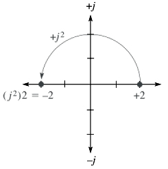
If you multiply the positive real value of +2 by j, the result is +j2. This multiplication has effectively moved the +2 through an angle to the axis.
Similarly, multiplying +2 by −j rotates it −90° to the −j axis. Thus, j is considered a rotational operator.
Mathematically, the j operator has a value of √−1. If +j2 is multiplied by j, you get
j22 = (√−1) (√−1)(2) = (−1)(2) =−2
This calculation effectively places the value on the negative real axis. Therefore, multiplying a positive real number by j2 converts it to a negative real number, which, in effect, is a rotation of 180° on the complex plane.
Ques.24. When the frequency of the voltage applied to a series RC circuit is increase, the impedance?
Increase
Decrease
Remain same
None of the above
Answer.2. Decrease
Explanation:-
As we know, capacitive reactance varies inversely with frequency.
The impedance of the RC circuit is given as
$Z = \sqrt {{R^2} + {X^2}_C} $
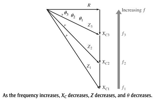
When XC increases, the entire term under the square root sign increases, and thus the magnitude of the total impedance also increases; and when XC decreases, the magnitude of the total impedance also decreases. Therefore, in a series RC circuit, Z is inversely dependent on frequency.
As the frequency is increased, XC decreases; so less voltage is dropped across the capacitor. Also, Z decreases as XC decreases, causing the current to increase. An increase in the current causes more voltage across R.
As the frequency is decreased, increases, XC so more voltage is dropped across the capacitor. Also, Z increases as XC increases, causing the current to decrease. A decrease in the current causes less voltage across R.
As the frequency increases, the voltage across Z remains constant because the source voltage is constant. Also, the voltage across C decreases. The increasing current indicates that Z is decreasing. It does so because of the inverse relationship stated in Ohm’s law i.e Z = Vs/I. The increasing current also indicates that XC is decreasing (XC = Vc/I). The decrease in Vc corresponds to the decrease in XC.
Since XC is the factor that introduces the phase angle in a series RC circuit, a change in XC produces a change in the phase angle. As the frequency is increased, becomes smaller, and thus the phase angle decreases. As the frequency is decreased, XC becomes larger, and thus the phase angle increases.
Ques.25. In series RC circuit the _____ leading _________
Voltage, Current
Power, Current
Current, Power
Current, Voltage
Answer.4. Current, Voltage
Explanation:-
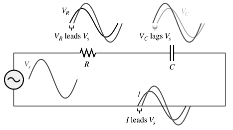
When a sinusoidal voltage is applied to a series RC circuit, each resulting voltage drop and the current in the circuit are also sinusoidal and have the same frequency as the applied voltage. The capacitance causes a phase shift between the voltage and current that depends on the relative values of the resistance and the capacitive reactance.
When a circuit is purely capacitive, the phase angle between the applied voltage and the total current is 90° with the current leading the voltage. When there is a combination of both resistance and capacitive reactance in a circuit, the phase angle between the applied voltage and the total current is somewhere between 0° and 90° depending on the relative values of the resistance and the capacitive reactance.
Ques.26. The circuit phase angle is the angle between the total _______ and the applied _______.
Voltage, current
Current, voltage
Current, Power
None of the above
Answer.2. Current, voltage
Explanation:-
The phase angle is the angle between the total current and source voltage. It may be positive or negative depending on whether the source voltage leads or lags the circuit current.
When a circuit is purely resistive, the phase angle between the applied (source) voltage and the total current is zero.
When a circuit is purely capacitive, the phase angle between the applied voltage and the total current is with the current leading the voltage.
When there is a combination of both resistance and capacitive reactance in a circuit, the phase angle between the applied voltage and the total current is somewhere between 0 and 90° depending on the relative values of the resistance and the capacitive reactance.
Ques.27. A capacitor with 150Ω of capacitive reactance is across an ac source. The impedance, expressed in polar form, is
Ques.28. A 12 kΩ resistor is in series with a 0.02 µF capacitor across a 1.2 kHz ac source. If the current is expressed in polar form as I = 0.3 ∠0° mA, what is the source voltage expressed in polar form?
Ques.29. An imaginary number exists only in the mind of the mathematician
True
False
It May be true or false
None of the above
Answer.2. False
Explanation:-
The product of two positive numbers, as well as two negative numbers, is positive, how can we find the square root of a negative number. Or, can we find a number such that, when it is multiplied by itself gives a negative number. Obviously not. But there arise situations where we have to find the square root of negative numbers.
Solving for x from the equation x2 +25 = 0 is such an instance. For enabling these operations, is taken and denoted by I, the first letter of the word imaginary (In fact it is the Greek letter iota). Using this notation, we can write the square root of negative numbers.
An imaginary number that when squared gives a negative result ie i(iota). Imaginary numbers do exist. Despite their name, they are not really imaginary at all.
Ques.30. For a certain load, the true power is 150 W and the reactive power is 125 VAR. The apparent power is