Ques.61. The total current in the Parallel RC circuit is expressed as
It = IR + IjC
It = IR − IjC
IR = It + IjC
None of the above
Answer.1. It = IR + IjC
Explanation:-
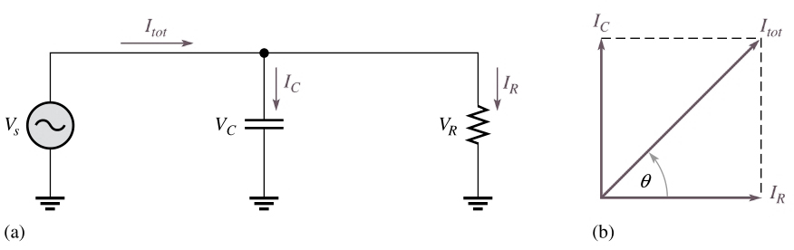
Phase Relationships of Currents and Voltages for the parallel RC circuit
Figure (a) shows all the currents in a basic parallel RL circuit. The total current It divides at the junction into the two branch currents, IR and IC. The applied voltage Vs appear across both the resistive and the inductive branches, so Vs, Vr, and VC are all in phase and of the same magnitude.
The current through the resistor is in phase with the voltage. The current through the capacitor leads the voltage and the resistor current by 90°. By Kirchhoff’s current law, the total current is the phasor sum of the two branch currents, as shown by the phasor diagram in Figure (b). The total current is expressed as
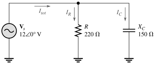
Ques.62. Find the total current in the Parallel RC circuit shown in the figure below
54.5 A − j80 A
80 mA − 54.5 mA
54.5 mA + j80 mA
54.5 mA − j80 mA
Answer.3. 54.5 mA + j80 mA
Explanation:-
From the given figure the resistor current, the inductor current, and the total current are
IR = Vs/R = 12∠0°/220∠0° = 54.5∠0° mA
IL = Vs/XC = 12∠0°/150∠90° = 80∠90° mA
It = IR + IjC
It = 54.5 mA + j80 mA
Ques.63. For conversion of a parallel RC circuit to Series RC circuit, the magnitude of ______ and _______ should be identical.
Resistance, Impedance
Impedance, Reactance
Reactance, Conductance
Impedance, Phase angle
Answer.4. Impedance, Phase angle
Explanation:-
For every parallel RC circuit, there is an equivalent series RC circuit for a given frequency. Two circuits are considered equivalent when they both present an equal impedance at their terminals; that is, the magnitude of impedance and the phase angle are identical.
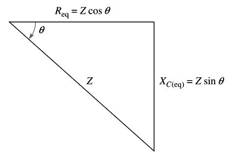
To obtain the equivalent series circuit for a given parallel RC circuit, we need to find the impedance and phase angle of the parallel circuit. Then use the values of Z and θ to construct an impedance triangle, shown in Figure. The vertical and horizontal sides of the triangle represent the equivalent series resistance and capacitive reactance as indicated. These values can be found using the following trigonometric relationships:
Req = Zcosθ
XCeq = Zsinθ
Ques.64. Convert the parallel circuit into a series form when the resistance is 18 kΩ and capacitance reactance is 27 kΩ.
Ques.65. When the value of the resistor in a series RC circuit is greater than the capacitive Reactance then
More energy is stored
More energy is dissipated
No energy loss
None of the above
Answer.2. More energy is dissipated
Explanation:-
When the resistance in a series RC circuit is greater than the capacitive reactance, more of the total energy delivered by the source is converted to heat by the resistance than is stored by the capacitor. Likewise, when the reactance is greater than the resistance, more of the total energy is stored and returned than is converted to heat.
Ques.66. In a series RC circuit, 12 V(RMS) is measured across the resistor and 15 V(RMS) is measured across the capacitor. The RMS source voltage is
Ques.67. An ac circuit consists of a resistor and a capacitor. To increase the phase angle above 45°, the following condition must exist:
R < XC
R = XC
R > XC
None of the above
Answer.1. R < XC
Explanation:-
The phase angle of an RC lead circuit is
φ =tan−1(XC/R)
To increase the phase angle we need to increase the value of capacitive reactance or decrease the value of resistance since capacitive reactance is directly proportional to the capacitive reactance.
XC > R
Ques.68. A resistor and a capacitor are in series across a 20 V ac source. Circuit impedance is 4.33 kΩ. The current flow in the circuit is
460 mA
92 mA
4.6 mA
460 mA
Answer.3. 4.6 mA
Explanation:-
Given
Z = 4.33 kΩ
V = 20 V
The total current in the circuit I
I = V/Z = 20/1.33
I = 4.6 mA
Ques.69. As the phase angle between applied voltage and total current ______ the power factor _____
Increase, Decrease
Increase, Increase
Decrease, Decrease
Increase, Remain same
Answer.1. Increase, Decrease
Explanation:-
The term Cosθ is called the power factor and is stated as
PF = Cosθ
As the phase angle between applied voltage and total current increases, the power factor decreases, indicating an increasingly reactive circuit. The smaller the power factor, the smaller the power dissipation.
Ques.70. A 47 Ω resistor and a capacitor with 150 Ω of capacitive reactance are in series across an ac source. The impedance, expressed in rectangular form, is
Z = 47 Ω − j150 Ω
Z = 197 Ω
Answer.2. Z = 47 Ω − j150 Ω
Explanation:-
Given
Resistance R = 47 Ω
Capacitive reactance XC = 150 Ω
The total impedance in rectangular form for series RC circuit is