Ques.41. Wien’s bridge is used to measure
- Power
- Energy
- Phase Angle
- Frequency✓
Wien’s Bridge Wien’s bridge is primarily used for the determination of an unknown frequency. However, it can be used for various other applications including capacitance measurement, in harmonic distortion analyzers, where it is used as the notch filter. and also in audio and HF oscillators. Wien’s bridge is frequency sensitive. Thus, unless the supply voltage is purely sinusoidal, achieving balance may be troublesome, since harmonics may disturb the balance condition. The use of filters with the null detector in such cases may solve the problem. Note:- The inductance of an inductive coil is generally measured by the usual inductive circuit like Maxwell-Wein Bridge, Hay Bridge, Anderson’s bridge, Owen’s Bridge The Anderson’s bridge gives an accurate measurement of the self-inductance of the circuit. De-Sauty’s Bridge is used to measure the value of unknown capacitance in terms of standard capacitance.
Ques.42. Ammeter and voltmeter are connected across the load in _______ and _______ respectively.
- Series, Parallel✓
- Parallel, Series
- Series, Series
- Parallel, Parallel
The Voltmeter is connected in parallel with the Load Voltage mean the potential difference between two points. V=IR ( ohms law) A voltmeter is used to determine the voltage across 2 points of resistance in a circuit. For this purpose, it obviously has to be in contact with both the points across its 2 ends to give the reading for the potential difference of the 2 points. If it is connected in series, it will be in contact with only 1 point at a time. However, voltmeters have very high resistance so that they pull the minimum current possible towards them, thus preventing a wrong current reading. Now if it is connected in series then no current will be there in the circuit due to its high resistance. Hence it is connected in parallel to the load across which the potential difference is to be measured. An ammeter is connected in series with the load To measure current, you want most of the current to pass through it. Hence ammeter is connected in series with the low resistance An ammeter measures the value of current flowing in the circuit, so current should flow inside the ammeter to give proper results. it acts like a closed switch so it indicates the current. And it has very low resistance to ensure the correct measurement of current in the circuit. If it is connected in parallel across any load then all current in the circuit will choose the lower resistive path (i.e ammeter) to cause its circuit to be damaged. Hence it is used in series.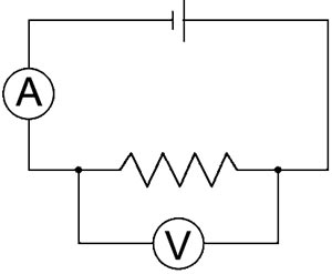
Ques.43. The deflection sensitivity of the CRO is 10 m/V. What is the value of the deflection factor (in V/m)?
- 10
- 0.1✓
- 1
- 0.01
The deflection sensitivity of a magnetic deflection cathode ray tube is defined as the amount of spot deflection on the screen when the potential of 1 volt is applied to the deflection plate. In most CROs, the deflection sensitivity is expressed as the ratio of input voltage to the length of the trace. In the electrostatic deflection, the spot la deflected on the screen by applying voltages on the vertical or the horizontal deflecting plates. The dc or peak-to-peak ac voltage applied to the deflects ing plates to displace the spot by 1 mm on the screen is termed the deflection factor. The reciprocal of the deflection factor is called the deflection sensitivity. The deflection factor la usually expressed in V/mm and deflection sensitivity in mm/V. Deflection sensitivity of the CRO is given as Deflection sensitivity = 1/deflection factor Deflection sensitivity = 1/10 =0.1m/V
Ques.44. The current required for full-scale deflection of a voltmeter is 10 mA. Find the sensitivity (in ohms/V) of the voltmeter.
- 100✓
- 10
- 0.01
- 0.001
The sensitivity of a voltmeter is given in ohms per volt. It is determined by dividing the sum of the resistance of the meter (Rm) plus the series resistance (Rs), by the full-scale reading in volts. In equation form, sensitivity is expressed as follows: Sensitivity (S) = (Rm + Rs) ⁄ Vfld or Sensitivity (S) = Sensitivity = Ohm/Volt = 1/Volt/Ohm = 1/Ampere S = 1/10 × 10−3 = 100A S = 100 ohm/volt
Ques.45. Calculate the fastest rise time (in ms) a sine wave can have to be reproduced by a CRO if the bandwidth ranges from 0 Hz to 10 Hz.
- 17.5
- 0.35
- 35✓
- 1.75
Bandwidth Instruments that measure AC waveforms generally have some maximum frequency above which the measurement accuracy is degraded. This frequency is the bandwidth of the instrument and is usually defined as the frequency at which the instrument’s response has decreased by 3 dB. Rise Time Ideally, waveforms such as square waves and pulses change the voltage level instantaneously. In reality, waveforms tales some time to make an abrupt change, depending on the bandwidth of the system and other circuit parameters. The amount of time it takes for a waveform to transition from one voltage to another is called rise time. (The rise time is normally measured at the 10% and 90% levels of the transition.) The bandwidth of a measuring instrument will limit the measured rise time of a pulse or square wave. For a typical instrument, the relationship between rise time and bandwidth is given by: Trise = 0.35/Bandwidth Trise = 0.35/10 = 0.035 = 35ms
Ques.46. Which of the following is NOT the correct representation of the balanced condition of the AC bridges?
- I1 = I3, I2 = I4
- |Z1| + | Z4| = |Z2| + |Z3|✓
- θ1 + θ4 = θ2 + θ3
- |Z1|| Z3| = |Z2||Z4|
A.C. bridges are electrical networks, based upon an extension of the Wheatstone* bridge principle, used for the determination of an unknown impedance by comparison with known impedances and for the determination of frequency. In general, they contain four impedance arms an A.C power supply and a balance detector which is sensitive to alternating currents. It is more difficult to achieve balance in an a.c. bridge than in a d.c. bridge because both the magnitude and the phase angle of impedances are related to the balance condition. Balance equations are derived by using complex numbers. A.c. bridges provide precise methods of measurement of inductance and capacitance, as well as resistance. The balanced condition of an A.C bridges The majority of well-known a.c. bridges are classified as four-arm bridges and consist of an arrangement of four impedances (in complex form, Z = R + jX), as shown in Figure. As with the d.c. Wheatstone bridge circuit, an a.c. the bridge is said to be ‘balanced’ when the current through the detector is zero (i.e. when no current flows between B and D ). if the current through the detector is zero, then the current I1 flowing in impedance Z1 must also flow in impedance Z2. Also, at balance, the current I4 flowing in impedance Z4, must also flow through Z3 At balance: The volt drop between A and B is equal to the vol drop between A and D, i.e. VAB = VAD i.e. I1Z1 = I4Z4 (both in magnitude and in phase) ———(1) The volt drop between B and C is equal to the vol drop between D and C, i.e. VBC = VDC i.e. I1Z2 = I4Z3 (both in magnitude and in-phase———-(2) Dividing equations 1 and 2 we get Z1Z3 = Z2Z4 Let θ1, θ2, θ3, θ4, be the phase angles. The product of the impedances must be carried out in the polar form where magnitudes get multiplied and phase angles get added. Z1∠θ1 × Z3∠θ3 = Z2∠θ2 × Z3∠θ4 Z1Z3 ∠θ1 + θ3 = Z2Z4 ∠θ2 + θ4 ∠θ1 + θ3 = ∠θ2 + θ4 Also when the bridge is balanced no current flow from the galvanometer hence I1 = I3, & I2 = I4 Thus the products of the magnitudes of the opposite arms must be equal while the sum of the phase angles of the opposite arms must be equal. The bridge must be balanced for both the conditions magnitude as well as phase. The phase angles depend on the components of the individual impedances. The phase angles are positive for the inductive impedances and negative for the capacitive impedances.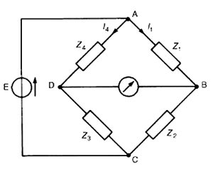
Ques.47. Determine the value of a shunt resistance (in Ohms) required to convert a galvanometer into an ammeter of reading up to15 A. The internal resistance of the galvanometer is 30 Ohms and the value of the current for a full-scale deflection is 0.3A.
- 0.84
- 0.74
- 0.61✓
- 0.52
The current range of a DC moving coil ammeter is extended by connecting a shunt Rs (low resistance) across the coil, the circuit as shown in Figure I = Total current = 15A The full-scale deflection current Im is given as Im =Rm +Rsh I×Rsh 0.3=(30+Rsh )15×Rsh Rsh =0.61ohms 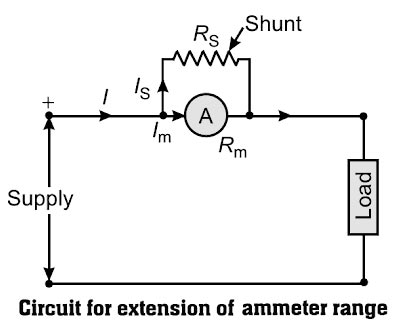
Im = full-scale deflection current of ammeter = 0.3
Ish = shunt current
Rm = resistance of the ammeter = 30Ω
Rsh = shunt resistance = ?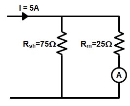
Ques.48. A 3 phase – 110 V motor has a power factor of 0.5. The two wattmeters connected measure the total input of 50 kW. Calculate the reading (in kW) of each wattmeter.
- 0, 150
- 100, 50
- 0, 50✓
- 50,50
Total reading of Two wattmeters is W = W1 + W2 = 50 = W1 + W2 ———(1) Power factor cosφ = 0.5 = φ = 60° The power factor of the wattmeter is given as $\tan 60 = \sqrt 3 \left( {\dfrac{{{w_1} – {w_2}}}{{{w_1} + {w_2}}}} \right)$ W1 + W2 = W1 − W2 W2 = 0 Putting the value of W2 in eauation 1 we get 50 = W1 + 0 W1 = 50 kW Hence the reading of wattmeter is 50, 0 Method 2 The reading of two wattmeters can be expressed as W1 = VLILcos(30 − φ) When PF is 0.5 (φ = 60°) W1 = VLILcos30° = Positive W1 + W2 = W1 = Total Power = 50 ∴ total power is measured by wattmeter W1 alone One wattmeter shows zero reading for cosφ = 0.5. For all power factors between 0 to 0.5 W2 shows negative and W1 shows positive, for lagging p.f. Hence the reading of wattmeter is 50, 0
W2 = VLILcos(30 + φ)
W2 = VLILcos90° = 0°
Ques.49. The inductance of a moving iron instrument is (10 + 6θ) μH, where θ is the deflection in radian from zero position. Assuming spring constant K = 10 × 10−6 Nm/Rad, the deflection (in rad) for a current of a 6 A is_____
- 10.8✓
- 10
- 9.8
- 9
The deflection in the moving iron instrument is given as $\theta = \dfrac{1}{2}\dfrac{{{I^2}}}{K}\dfrac{{dL}}{{d\theta }}$ Where I = current = 6 A K = Spring constant = 10 × 10−6 Nm/rad dl/dθ = change in Inductance Change in the inductance dl/dθ = d(10 + 6θ) ⁄ dθ μH dl/dθ = 6 × 10⁻⁶ H $\begin{array}{l}\theta = \dfrac{1}{2} \times \dfrac{{{6^2}}}{{10 \times {{10}^{ – 6}}}} \times 6 \times {10^{ – 6}}\\\\\theta {\rm{ }} = {\text{ 10.8 Radian}}\end{array}$
Ques.50. What will happen to the operating torque of the moving iron instrument, if the current through the operating coil is halved?
- Halved
- Doubled
- Remain same
- One-fourth✓
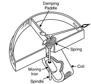
This type of instrument is principally used for the measurement of alternating currents and voltages, though it can also be used for d.c. measurements. There are two types of moving-iron instruments. (i) Attraction type in which a single soft-iron vane (or moving iron) is mounted on the spindle and is attracted towards the coil when operating current flows through it. (ii) Repulsion type in which two soft-iron vanes are used; one fixed and attached to the stationary coil while the other is movable (i.e. moving iron) and mounted on the spindle of the instrument. When operating current flows through the coil, the two vanes are magnetized, developing similar polarity at the same ends. Consequently, repulsion takes place between the vanes and the movable vane causing the pointer to move over the scale. Attraction Type Instrument Construction The sectional view of an attraction-type moving iron instrument is shown in Figures It consists of a stationary hollow cylindrical coil. An oval-shaped soft iron piece is mounted eccentrically to the spindle to which a pointer (needle) is attached. The controlling torque is provided by the spring control method while damping torque is provided by air friction, as shown in Figures Working of Attraction Type. When the instrument is connected in the circuit to measure current or voltage, the operating current flowing through the coil sets up a magnetic field. In other words, the coil behaves like a magnet and therefore it attracts the soft-iron piece towards it. The result is that the pointer attached to the moving system moves from zero position. The pointer will come to rest at a position where deflecting torque is equal to the controlling torque. If the current in the coil is reversed, the direction of the magnetic field also reverses and so does the magnetism produced in the soft-iron piece. Hence, the direction of the deflecting torque remains unchanged. For this reason, such instruments can be used for both d.c. and a.c. measurements. Deflecting torque:- Torque in the attraction-type moving-iron instrument, the deflecting torque is due to the force of attraction between the field of the coil and the moving iron disc. The magnetization of the iron disc or pole strength is proportional to the magnetic field strength H. The force F pulling the disc inwards is proportional to the Pole strength M of the disc and field strength H. Therefore the deflecting torque Td ∝ MH M ∝ H H ∝ I Td ∝ I2 Hence the deflecting torque depends on the attraction between the field of the coil and the moving iron disc. That is, in an ammeter, the torque is roughly proportional to the current squared. The instrument, therefore, has the square-law response. The deflection is proportional to the mean value of the square of the current. When used on AC, it indicates the RMS or effective value of current (or voltage). Now coming back to question when the current is halved i.e T ∝ (1/2)2 T ∝ 1/4 So when the current is halved the torque in the moving iron instrument becomes 1/4thMoving – Iron (M.l.) Ammeters and Voltmeters