Ques.21. What will happen to the inductance, if the number of turns of the coil is decreased? (SSC-2013 Set-3)
Increase
Decrease
Remain Same
None of these
Answer.2. Decrease
Explanation:-
The inductance of the is given as
L = N2 ⁄ Reluctance
i.e L ∝ N2
Since the inductance is directly proportional to the number of turns in the coil, So if the number of turns will decrease the inductance will also decrease
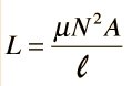
The self-inductance of the coil can also be written as
L = μN2A/I = L1
where
N is the number of turns of the solenoid
A is the area of each turn of the coil
l is the length of the solenoid
and μ is the permeability constant
The inductance of a coil can be reduced by one of the following methods:
By taking some turns off the coil.
By stretching out of the coil until it has a greater length.
By decreasing the area of the coil since less coil area offers more opposition to the formation of magnetic field flux for a given amount of field force.
The way the turns are arranged:- a short thick coil will have higher self-inductance than a long, thin one.
Presence of a magnetic circuit:- If the coil is wound on an iron core, the same current will set up a greater magnetic flux and the self-inductance will be higher.
Ques.22. If the area of cross-section is reduced to half of its value, then what will happen to the flux density? (SSC-2013 Set-3)
Doubled
Halved
Remain the same
One-fourth
Answer.1. Doubled
Explanation:-
Magnetic flux is the amount of magnetic field (or the number of lines of force) produced by a magnetic source. The symbol for magnetic flux is φ. The unit of magnetic flux is the Weber,* Wb.
Magnetic flux density is the amount of flux passing through a defined area that is perpendicular to the direction of the flux.
or
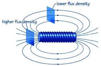
The ‘closeness’ of a field’s lines of the magnetic field indicates the intensity of the field at any given point. This is termed the magnet flux density (symbol: B) of the field at that particular point. Just as with a permanent magnet, the flux density is always greatest in the areas nearest the poles of the coil as shown in the figure.
From Figure, it can be seen that more Lines of flux pass through the shaded rectangle near poles, than through the rectangle of the identical cross-sectional area placed midway along with the coil. So can define flux density as the ‘ flux per unit is expressed as follows:
B = φ/A Wb/m2 or tesla
From the above equation, the magnetic flux density is inversely proportional to the area hence if the area is reduced to half then the magnetic flux density will become double.
B = φ/1/2 = B = 2φ
Ques.23. Calculate the value of the flux leakage coefficient, if φg is the air gap flux and φa is the flux in the iron core. (SSC-2013 Set-3)
φg/φa
φa/φg
φg × φa
φg + φa
Answer.2. φa/φg
Explanation:-
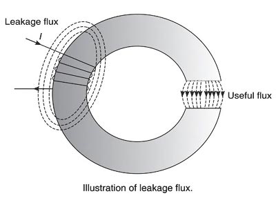
The flux which does not follow the desired path of magnetic material is called leakage flux. Generally, it is not possible to confine the entire flux to the iron path only, unlike an electric current that can be confined to a wire by providing proper insulation. In any magnetic circuit, it is impossible to avoid magnetic leakage since there is no magnetic insulator available in practice. For example, the air is a good insulator of electricity, though, it conducts magnetic flux. The flux in the air gap is known as a useful flux because it can be utilized for practical purposes.
The figure shows an iron ring wound with a coil and having a narrow air gap. The total flux produced by the coil does not pass through the air gap as some of it leaks through the air surrounding the ring. These flux lines are called leakage flux.
Therefore the part of the magnetic flux that has its path within the magnetic circuit is known as the useful flux or main flux and that taking other paths is called leakage flux. This phenomenon of wastage of some flux is called magnetic leakage. Sum of the two parts is called the total flux produced.
The ratio of the total flux produced by the magnet to the main flux is called leakage coefficient or leakage factor.
or
The ratio of total flux (flux in the iron path) to the useful flux (flux in the air gap) is known as leakage factor (λ).
Mathematically, leakage factor can be written as
Leakage factor λ = φT ⁄ φm = Total useful flux ⁄ Main flux = (φL + φm) ⁄ φm
Where
φL = Leakage flux
φm = Main flux
φT = Total flux
or
Leakage factor λ = (Flux in the Iron Path) / (Flux in the air Gap)
λ = φa ⁄ φg
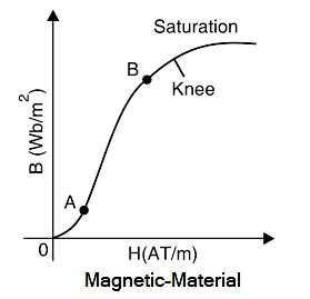
Ques.24. The graph shown below represents the B-H curve for_______ (SSC-2013 Set-3)
Glass
Steel
Iron
Air
Answer.4. Air
Explanation:-
B-H Curve (or Magnetisation Curve)
The B-H curve (or magnetization curve) indicates the manner in which the flux density (B) varies with the magnetizing force (H) and the relationship is given as
B = μrμoH
Where
μois called permeability of free space or magnetic space constant. Its value is 4π × 10-7 H/m,
μr = Relative permeability of medium which is equal to 1 for all non-magnetic material
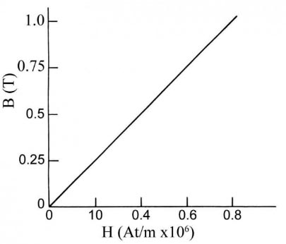
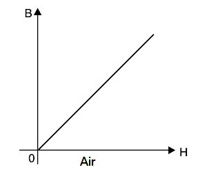
(i) For non-magnetic materials. For non-magnetic materials (e.g. air, copper, wood etc.), the relationship between B and H is
B = μoH
Hence the B-H curve of a non-magnetic material is a straight line passing through the origin as shown in Fig. because the curve never saturates no matter how great the flux density may be. and a large m.m.f. is required to produce a given flux in the non-magnetic material (e.g. air), also µo = 4π x 10-7 is constant quantity, therefore, B ∝ H
(ii) For magnetic materials. For magnetic materials (e.g., iron, steel, etc.), the relation between B and H is given by:
B = μrμoH
Here μr is not constant but varies with flux density. Consequently, the B-H curve of a magnetic material is non-linear. Fig. shows the general shape of the B-H curve of a magnetic material. The non-linearity of the curve indicates that the relative permeability (μr = B/μoH) of a magnetic material is not constant but depends upon flux density.
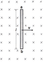
Ques.25. A conductor of length 0.6 m is situated at the right angle to a uniform magnetic field of flux density 4 Wb/sq.m. The conductor is moving with a velocity of 50m/s. Calculate the emf induced (in V) in the conductor. (SSC-2013 Set-3)
100
115
118
120
Answer.4. 120
Explanation:-
The emf induced in a straight conductor of length l moving with velocity v perpendicular to a magnetic field B is
E = Blvsinθ
Where E is the generated voltage =? B is the magnetic flux density = 4 Wb/m2 l is the length of a conductor in the magnetic field = 0.6 m v is the velocity of the conductor perpendicular to the magnetic lines = 50m/s
The value of sinθ is maximum at 90 degrees i.e When the coil is perpendicular to the field axis. i.e
E = Blv
E = 4 × 0.6 × 50 = 120 V
E = 120 Volts
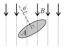
Ques.26. A flux of 2mWb passes through a strip of length and breadth 10 cm and 20 cm respectively. It is placed at an angle of 30 degrees to the direction of uniforms magnetic field. What is the magnetic flux density (in T)? (SSC-2013 Set-3)
0.1
0.115
0.9
1
Answer.2. 0.115
Explanation:-
Accordingly, the magnetic flux φ passing through a surface of area A with a normal at an angle θ to a magnetic field of flux density B is given by:
φ = B.A.Cosθ
Where
φ = Magnetic flux = 2mWb = 2 × 10⁻³ Wb
A = Area = (Length × Breadth) = (10 × 20) = 200 cm2 = 200 × 10−4 m2
θ = Angle to the magnetic field = 30°
B = Magnetic flux density =?
2 × 10−3 = B × 200 × 10−4 × Cos30°
B = (2 × 10⁻³ ) ⁄ (200 × 10−4) × 0.866
B = 0.115 Tesla or Wb/m2
Ques.27. A 600-turns coil has an inductance of 0.8 H. if one-fifth of the turns are removed, then determine the new inductance (in H). (SSC-2013 Set-3)
0.512
1.25
2
2.5
Answer.1. 0.512
Explanation:-
The inductance of a coil of wire is given by
Where
N = Number of turns in the coil
μ = permeability of the core material
A = Area of the coil
l = length of the coil
Let the Initial Inductance and turns of the coil are L1 & N1 and the New length of the coil be L2 & N2
If one-fifth of the turns are removed, then the remaining turns are
N2 =(1 − 1/5) = 4/5.N1
Since L ∝ N2
∴ L1 ⁄ L2 = (N1 ⁄ N2)2
0.8 ⁄ L2 = (N1 ⁄ 4/5 × N1)2
0.8 ⁄ L2 = (5 ⁄ 4)2
L2 = 0.8 × 16 ⁄ 25 = 0.512 H
L2 = 0.512 H
Ques.28. A magnetic circuit of reluctance 3000 A-turns/Wb is wounded by a wire of 400 turns. Determine the average E.M.F induced (in V) in the coil, if the current of 2 A is flowing in the coil is reversed in 15s. (SSC-2013 Set-3)
14.22
16.28
17.96
19.62
Answer.1. 14.22
Explanation:-
The Relation Between the Inductance and the Reluctance is
L = N2/ℜ
Where
N = Number of turns
ℜ = Reluctance of the coil
L = (400)2 ⁄ 3000
L = 53.33 H
Hence the Average Induced EMF will be
E = L.Δi ⁄ t
Where
L is the inductance of the coil = 53.33 H
t = time = 15 sec
Δi is the change in current in A
Now change in current
Δi = 2 − (−2) = 4A (since the current is reversed)
Putting all the value in the equation
E = (53.33 × 4) ⁄ 15
E = 14.22 Volt
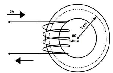
Ques.29. For the figure shown below, the permeability in the core is 4 × 10⁻⁴ Wb/A-turns-m.What is the value of flux density (in T) in the core? (SSC-2013 Set-3)
0.2
0.382
0.6
1
Answer.2. 0.382
Explanation:-
MAGNETIC FIELD INTENSITY
Magnetic field Intensity (H) is also called Magnetic field Strength, Magnetic Intensity, Magnetic field, Magnetic Force and Magnetization Force.
Magnetic field Intensity is represented by symbol H and is measured in ampere-turns per meter (At/m).
Relation Between Magnetic Flux Density and Field Intensity
At any point in a magnetic field, field strength or field intensity H is the force maintaining the magnetic flux and producing a particular value of flux density B at that point. Hence the field intensity H is the cause and the flux density B the effect. Thus the flux density can be assumed proportional to field intensity in the magnetic field i.e. in free space,
B = μoH Tesla
B = 4 × 10-4 × 9.55 × 102
B = 0.382 Tesla
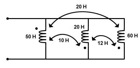
Ques.30. Calculate the total inductance (in H) of the circuit given below. (SSC-2013 Set-3)