
SSC JE Single Phase Induction Motor Solved Question (2021-2009)
Ques.1. A hysteresis Motor (SSC-2018 Set-1)
- Is not a self-starting motor
- Is a constant speed motor
- Need DC excitation
- Can not be run in reverse speed
Answer.2. Is a constant speed motor Explanation:- The hysteresis motor can be considered as a self-starting synchronous motor. From the time of starting until it reaches synchronous speed, the motor produces a synchronizing torque and an ideally flat speed/torque characteristic. Due to the absence of slots and teeth on the rotor, the operation of this motor is smooth and quiet. The motor behavior is similar to that of a conventional synchronous motor but there is no excitation winding on the rotor or permanent magnets, giving the motor a high efficiency and power factor. These characteristics make it ideal for many industrial applications, such as in electronic and medical equipment, tape and video recorder drives, computer drives, clocks, gyroscope rotors for inertial navigation, robotics and other special applications where precision and reliability are required.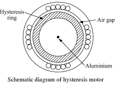
Ques.2. In a Hysteresis Motor, the rotor must have (SSC-2018 Set-1)
- Retentivity
- Resistivity
- Susceptibility
- None of these
Answer.1. Retentivity Explnation:- The rotor of the Hysteresis Motor is the smooth cylindrical type which is made up of hard magnetic material like chrome steel or alnico for high retentivity (it is the capacity of an object to retain magnetism after the action of the magnetizing force has ceased. This requires selecting a material with high hysteresis loop area. The rotor does not carry any winding. The stator construction is either split phase type or shaded pole type. The motor starts rotating due to eddy current and hysteresis torque developed on the rotor At synchronous speed, there is no induced emf in the rotor, as the stator synchronously rotating field and the rotor is stationary with respect to each other. In the absence of induced eddy current, the torque due to eddy current is zero. At synchronous speed, the rotor torque is only due to the hysteresis effect. When the rotor rotates at synchronous speed, the stator revolving field flux induces Poles on the rotor. Due to the hysteresis effect, the rotor polarities linger an instant after the stators
Ques.3. In a split-phase Motor (SSC-2018 Set-1)
- The starting winding is connected through a centrifugal switch
- The running winding is connected through a centrifugal switch
- Both starting and running windings are connected through the centrifugal switch
- The centrifugal switch is used to control the supply voltage
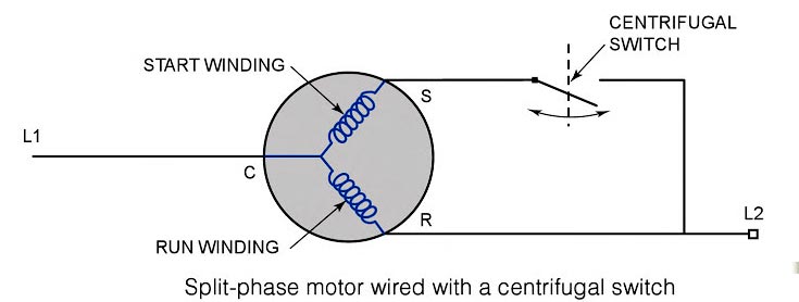
Answer.1. The starting winding is connected through a centrifugal switch Explanation:- Split-phase motors also referred to as induction-star induction-run (ISIR) motors, have a relatively low starting torque compared with the other single-phase motors but more torque than the shaded-pole motor. They range in size from 1/20 horsepower to abort 1/3 horsepower. Split-phase motors get their name from the fact that a single power supply is split between two individual windings — the run and the start — to produce the necessary torque to start the Motor. A split phase induction motor is provided with the main winding and auxiliary or start winding placed in space quadrature and are connected in parallel to a single-phase supply. The main winding has a low resistance and high reactance whereas the auxiliary winding has a high resistance and low reactance. The auxiliary winding is effective during the starting of the motor and is disconnected from the supply when the motor attains 75 percent of its synchronous speed. A centrifugal switch, S is used to disconnect the auxiliary winding from the source as shown in Fig. Under the normal running condition, only the main winding is effective. The run winding is energized whenever the motor is energized. This winding has a lower resistance than the start winding, which is only in the circuit long enough to help the motor start. For the motor to start, both the start and run windings must be energized. When both windings are energized, the current flows through each of the windings at a different rate, creating a phase shift. The phase shift is measured in electrical degrees and is often referred to as the phase angle. The larger the phase angle, the more starting torque a motor has. For a point of future reference, a split-phase motor, as just described, has a phase angle of about 30° degrees. If the run and start windings were constructed and configured exactly the same, with the same size wire and the same number of turns, the phase angle would be zero, the magnetic field would have no imbalance, and the motor would not start. Once the split-phase motor has started, the start winding must be removed from the electric circuit. The start winding is designed to be energized for only a short time and can become damaged if it is not de-energized. One commonly used device to remove the start winding from the circuit is the centrifugal switch (Fig.), which opens and closes its contacts depending on the speed of the motor. The electrical contacts on the switch are connected in series with the start winding and are normally closed. When the voltage is initially applied to the motor, both the start and run windings are energized and the motor begins to turn. Once the motor has reached a speed equal to about 70 percent of its rated speed, the contacts oi the centrifugal switch open, de-energizing the start winding. The run winding, or main winding, is now the only winding energized, and the motor continues to run in this fashion since the turning rotor now creates the imbalance needed to keep the motor running. When the motor is de-energized, it begins to slow down and the centrifugal switch closes in preparation for the next startup. Other components can be added to the split-phase motor to increase its torque, as well as its range of applications such as the capacitor, potential relay etc.SPLIT-PHASE MOTORS
Ques.4. Starting winding of a single-phase motor of a refrigerator is disconnected from the circuit by means of a (SSC-2018 Set-1)
- Magnetic Relay
- Thermal Relay
- Centrifugal Switch
- None of these
Answer.1. Magnetic Relay Explanation:- The function of the starting relay provided in the refrigerator is to start the split-phase induction motor by connecting the auxiliary winding or starting winding across the main supply in addition to the main winding at the time of starting. This helps to make the split-phase inflection motor as the self-induction motor is unable to start. The first method of disconnecting the starting winding of a split-phase motor is already discussed in the above Question i.e Question Number 63. Another method of disconnecting the auxiliary winding when the motor has picked up speed is by using an electromagnetic relay as has been shown in Fig The torque required to start the motor is significantly more than needed in the running condition At the starting time of the motor, electrical power is given to start relay and winding of the motor. It also provides current to the starting winding of the motor. The starting winding provides sufficient torque so that the motor starts running. As the motor speed increases, the torque requirement decreases and thereby the current required by the motor also decreases. The current in starting relay is not able to hold the relay and it gets released which opens the starting winding contacts. Therefore, the starting winding gets disconnected.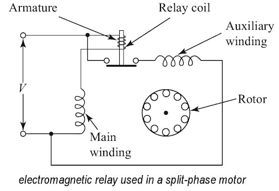
Ques.5. If the centrifugal switch does not open at 70 to 80 percent of the synchronous speed of the motor, it would result in. (SSC-2018 Set-1)
- Damage to the starting winding
- Damage to the centrifugal switch
- Overloading of running winding
- None of these
Answer.1. Damage to the starting winding Explanation:- All split-phase motors have a start and run winding. The start windings must be disconnected from the circuit within a very short period of time or they will overheat. Several methods are used to disconnect the start windings. The centrifugal switch is the most common method in open motors; however, electronic start switches are sometimes used. The centrifugal switch is used to disconnect the start winding from the circuit when the motor reaches approximately 75% of the rated speed. A centrifugal switch is a mechanical device attached to the end of the shaft with weights that will sling outward when the motor reaches approximately 75% speed. For example, if the motor has a rated speed of 1725 rpm, the centrifugal weights will change position at 1294 r.p.m (1725 x 0.75) and open a switch to remove the start winding from the circuit. This switch is under a fairly large current load, so a spark will occur. If the switch fails to open its contacts and remove the start winding, the motor will draw too much current, and the overload device will cause it to stop. When the motor is de-energized, it will slow down and the centrifugal switch will close its contacts in preparation for the next motor starting attempt. The more the switch is used, the more its contacts will burn from the arc. If this type of motor is started many times, the first thing that will likely fail is the centrifugal switch. This switch makes an audible sound when the motor starts and stops. Hence if the starting switch fails to open when needed, the starting winding mill almost always overheats and burns out.
Ques.6. The speed of the ceiling fan is about (SSC-2018 Set-1)
- Upto 10 RPM
- Upto 200 RPM
- Upto 450 RPM
- Upto 10000 RPM
Answer.3. Upto 450 RPM Explanation:- The ceiling fan use a single-phase induction motor ( capacitor start and capacitor Run Motor) the speed of ceiling fan is about 450 RPM and the supply rating is between 55 – 120 Watts.
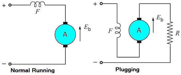
Ques.7. During plugging, external resistance is also introduced into a circuit to limit the flowing_____ (SSC-2018 Set-2)
- Current
- Voltage
- Current and voltage Both
- None of these
Answer.1. Current Explanation:- The disadvantages of this method are: 1. The kinetic energy of the motor is dissipated in the external resistance in the form of heat. So, this method of braking is inefficient. 2. The braking in this method fails in case of failure of the supply.
Ques.8. Reduction in the capacitance of a capacitor-start motor result in reduced_____ (SSC-2018 Set-2)
- Noise
- Speed
- Starting Torque
- Armature Reaction
Answer.3. Starting Torque Explanation:- Capacitor-Start Motors The capacitor start motor is identical to the split-phase motor in both construction and operation, except that a capacitor is installed in series with the starting winding, as shown in Fig. Also, the starting winding of the capacitor start motor is usually wound with larger wire than that used for the starting winding of the split-phase motor. The use of a capacitor in series with the starting winding causes the current in this winding to lead the voltage, whereas the current in the running winding lags the voltage by virtue of the high inductance of that winding. With this arrangement. the phase displacement between the two windings can be made to approach 90 electrical degrees so that we two-phase starting is achieved. For this reason, the starting torque of the capacitor start motor is very high, which makes it an ideal drive for the small compressor that must be started under full load. So if the low value of the capacitor is used in the motor the phase angle between the starting and running winding will be reduced and the motor can’t generate enough torque to rotate the motor.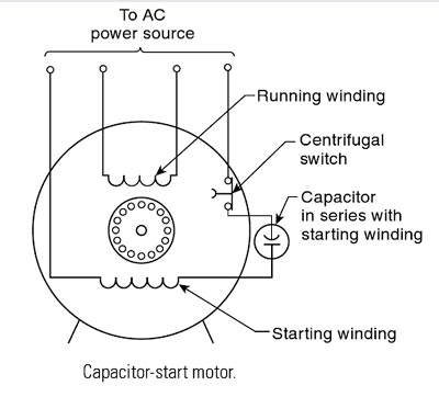
Ques.9. A single-phase induction motor with only the main winding excited would exhibit the following response at synchronous speed. (SSC-2018 Set-2)
- Rotor current is zero
- Rotor current is non-zero and is at slip frequency
- Forward and backward rotating fields are equal
- The forward rotating field is more than the backward rotating field
Answer.4. The forward rotating field is more than the backward rotating field Explanation:- The double-field revolving theory is proposed to explain the phenomenon that a single-phase induction motor is not self-starting but once rotated in one direction, it will continue to rotate in that direction. This theory is based on the fact that an alternating sinusoidal flux (φ = φm cos wt) can be represented by two revolving fluxes, each equal to one-half of the maximum value of alternating flux (i.e. φm /2) and each rotating at synchronous speed (Ns = 120f/P; ω = 2πf) in opposite directions as shown Rotor at standstill. Consider the case that the rotor of the single-phase induction motor is stationary and the stator is connected to a single-phase supply. The rotor e.m.f.s induced by the two revolving fields will be in opposite directions. At standstill, the slip in either direction is the same (s = 1) and so is the rotor impedance. Therefore, the starting currents in the rotor conductors are equal and opposite. This means that starting torque developed by one revolving field is equal and opposite to that developed by the other revolving field. As a result, the starting torque is zero i.e. a single-phase induction motor is not self-starting. The single-phase induction motor is not self-starting and it is undesirable to resort to the mechanical spinning of the shaft or pulling a belt to start it. To make a single-phase induction motor self-starting, we should somehow produce a revolving stator magnetic field. This may be achieved by converting a single-phase supply into a two-phase supply through the use of an additional winding. When the motor attains sufficient speed, the starting means (i.e. additional winding) may be removed depending upon the type of the motor. As a matter of fact, single-phase induction motors are classified and named according to the method employed to make them self-starting. (ii) Rotor running:- The existence of these two fluxes (forward and backward) rotating in opposite directions can be verified by supplying a fractional horsepower in a single phase induction motor with rated voltage. The motor does not start, but if the shaft la turned by hand, say in the clockwise direction, the rotor picks up speed. This means that the rotor conductors are rotating in the direction of that field which rotates in the clockwise direction. When the motor is braked and stopped without switching off the supply, the rotor remains at rest. If now the shaft is turned by hand in anti-clockwise Direction, the motor picks up speed in that direction which means that the rotor conductors are now rotating in the direction of the other field. The flux rotating in the clockwise direction (i.e. the direction of spinning) is called the forward rotating flux (φf) and that in the other direction is called the backward rotating flux (φb). The forward rotating flux has synchronous speed Ns (= 120 f/P) and the synchronous speed of rotating backward flux (anticlockwise) is –Ns. Slip in forward Direction:- Sf = (Ns – N)/Ns = s Slip in backward Direction:- Sb = (–Ns – N)/–Ns = s Sb = (2Ns + Ns + N)/Ns Sb = (2 – s) At standstill, N = 0 so that Sf = Sb = 1. For forward rotating flux, the slip is s (less than 1) and for backward rotating flux, the slip is 2 – s (greater than 1). We know that in a 3-phase induction motor, the torque developed is directly proportional to effective rotor resistance. The effective rotor resistance is R2/s in the forward direction and R2/2 – s in the backward direction. Therefore, the resultant torque in the single-phase induction motor will be in the direction of the forward rotating flux (clockwise in this case). Thus if the single-phase induction motor is once rotated, it will develop the torque in the direction in which it has been rotated and will function as a motor. The presence of the backward rotating field in a purely single-phase induction motor has a lot of disadvantages: It is observed that with only main field energized, the single-phase induction motor will not start. However, if an external torque moves the motor in any direction, the motor will begin to rotate. The absence of a rotating magnetic field is due to only one winding, in order to produce a rotating magnetic field, the motor should have at least two windings with currents which differ in phase. So what is needed is a second (auxiliary) winding, with currents out of phase with the original (main) winding, to produce a net rotating magnetic field. So if the single phase induction motor is made to rotate at synchronous speed and the starting winding is disconnected and only the main winding is excited then the forward rotating field is more than the backward rotating field and the motor will start in the forward direction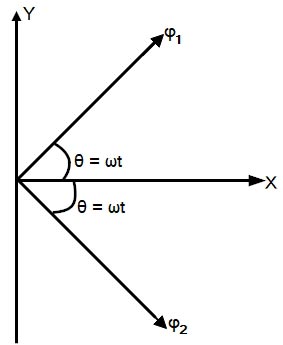
Ques.10. The electric motor used in portable drills is_______ (SSC-2018 Set-2)
- Capacitor Run Motor
- Hysteresis Motor
- Universal Motor
- Repulsion Motor
Answer.3. Universal Motor Explanation:- Universal motors are essentially DC motors with series windings. The motors can be operated from either a DC or an AC source. Since the torque in a DC motor is proportional to both the armature and the field currents, connecting the windings in series ensures that the polarity of both the armature and field windings reverses simultaneously producing unidirectional torque. Universal motors can operate at up to 20,000 rpm and are widely used for vacuum cleaners, portable drills, food mixers, and fans. These motors tend to be noisy when supplied from an AC source with high torque ripples and are also not very efficient. A triac connected in series with the supply can be used to regulate the supply voltage, thereby enabling the use of these machines for low-cost variable-speed applications.