Ques 91. The disadvantage of a short-pitched coil is that ______
Harmonics are introduced
Waveform becomes non-sinusoidal
Voltage around the coil is reduced
None of the above.
Answer. 3.Voltage around the coil is reduced
Explanation:-
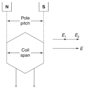
In the case of full pitch winding the pole pitch and coil span are equal to 180 degrees.
Full pitch winding
As we can see in the figure one coil cut N pole and other coil cut S pole which results in the phase difference of 180 degrees.
The full pitch winding offer full induced emf but it causes harmonic distortion.
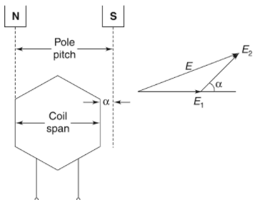
Talking about Short pitch winding the pole pitch is slightly less than to pole pitch by an angle α.
Short pitch winding
For reducing 3rd harmonic from generated emf
Cos(3α/2) = 0
3α/2 = π/2 α = π/3 = 60°
Therefore the value of α should be 60 degrees.
Some advantages of short-pitch winding are
Due to the shortening span, the copper required is less.
Low copper losses
Improve waveform due to the reduction in harmonic
Fractional Pitch winding reduces sparking in DC machines
Disadvantages of Short Pitch Coil:
Since in a fractional pitch winding, the two sides of a given coil are not at the corresponding points under the adjacent poles.Hence the e.m.f. induced in the two sides is slightly out of phase and the coil e.m.f. is less than if the full pitch was used with the same number of turns. In order to compensate for this reduction in Generated EMF, more number of turns, and therefore more copper is required.
Ques 92. The per-phase D.C armature resistance of an alternator is 0.5 ohm. The effective AC armature resistance would be about?
0.25 ohms
0.5 ohms
1 ohm
0.75 ohms
Answer. D.0.75 ohms
Explanation
Since there are harmonics generated in individual coils of the alternator windings, some high frequencies are present. Due to skin effect, the effective a.c resistance of armature winding is greater than its d.c. resistance. The factor of difference varies according to the base frequency and winding arrangement and is from 1.2 to 1.8. It is the usual practice to take a.c. armature resistance as 1.5 times the d.c. resistance for 50 Hz machine.
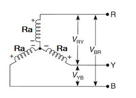
Consider the star connection. Every armature winding has its own resistance. The effective resistance of an armature winding per phase is denoted as Ra Ω/ph.
Generally, the armature resistance is measured by applying the known d.c. voltage and measuring the d.c. current through it. The ratio of applied voltage and measured current is the armature resistance. But due to the skin effect, the effective resistance under a.c. conditions are more than the d.c. resistance. Generally the effective armature resistance under a.c. conditions are taken 1.25 to 1.75 times the d.c. resistance. While measuring the armature resistance, it is necessary to consider how the armature winding is connected whether in star or delta. Consider a star connected armature winding as shown in Fig. When the voltage is applied across any two terminals of an armature winding, then the equivalent resistance is the series combination of the two resistance of two different phase windings, ... RRY = Resistance between R-Y terminals = Ra + Ra = 2Ra where Ra = armature resistance per phase ... Ra = RRY/2 Ω/ph Thus in star connected alternator, the armature resistance per phase is half of the resistance observed across any two line terminals. Thus per phase DC armature resistance is half of the measured value Ra = 5/2 = 0.25Ω
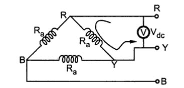
Consider the delta-connected alternator as shown in Fig.
When the voltage is applied across any two terminals, then one phase winding appears in parallel with the series combination of the other two. Hence the equivalent resistance across the terminals is the parallel combination of the resistance Ra and 2Ra. $\begin{array}{l}{R_{RY}} = {R_a}||2{R_a}{\rm{\Omega /Ph}}\\\\ = \dfrac{{{R_a} \times 2{R_a}}}{{{R_a} + 2{R_a}}}\\\\{R_a} = \dfrac{3}{2}{R_{RY}}\end{array}$ Therefore, per phase d.c. armature resistance is Ra = (3 × 1) ⁄ 2 = 1.5Ω
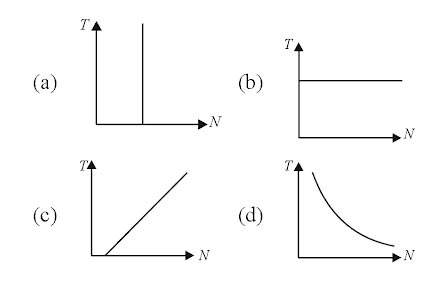
Ques 95. Which of the following graph represents the speed-torque characteristics of a synchronous machine.
Answer. A.
Explanation:-
The speed-torque curve is a horizontal line (constant speed) pull out (maximum) value. As we know that the synchronous machine runs at the constant speed, i.e N = Ns for all value of torque. Hence option a is correct.
Ques 96. For cooling large size generators hydrogen is used because
It offers reduced fire risk
It is light in weight
It is of high thermal conductivity
All of the above
Answer. 4.All of the above
Explanation:-
Why is hydrogen used for Alternator cooling?
Hydrogen is the least expensive, with less weight, high thermal conductivity, less density, and less viscosity. Less weight, less density & less viscosity are attributes to its flow rate. High thermal conductivity helps in better heat exchange. The least expensive help in balance sheets, more power in fewer investments.
In order to reduce the high temperature of the alternator hydrogen gas is used as a coolant. The coolant, Hydrogen gas is allowed to flow in a closed cyclic path around the rotor. Heat exchange takes place and the temperature of hydrogen gas increases, for better cooling of the rotor in the next cycle it has to be cooled. Cooling of hydrogen gas is done by passing it through heat exchangers generally constituted with water. Now Hydrogen gas after cooling is allowed to pass through driers ( mainly silica gel which absorbs moisture) and allowed to pass again through the rotor.
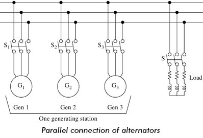
Ques 97. The advantages of the parallel operation of the alternator are:
Increase Efficiency
Maintained continuity of supply
Ease in the future extension
All of the above
Answer. 4.All of the above
Explanation:-
The demand for power is increasing day by day. It is a challenge for power engineers to meet the power demand of customers. A single alternator cannot meet the power demand. To meet the excess power demand, additional alternators are connected in parallel. If a single alternator can meet the power demand, an outage of the alternator will cause an interruption of power supply. On the other hand, the paralleling of alternators ensures the supply of a part of the total demand when one alternator is out of order.
Reasons for Paralleling of Alternators
The reasons for paralleling are
A single alternator may not meet the local or regional power requirements.
It is possible to shut down one or more alternators for scheduled or emergency maintenance when the alternators are operating in parallel. The load can be supplied.
At part load, one or more alternators are shut down and the remaining load is carried out with few machines efficiently because alternators are inefficient at part load.
It is possible to handle load growth by adding alternators without disturbing the original installation.
The available machine prime movers and alternators can be matched to obtain economical cost and reliable use.
Advantage of Parallel Operation of Synchronous Generators
The following are the advantages of connecting a large number of synchronous generators in parallel to supply a common load:
Continuity of Supply and Maintenance: Repair and maintenance of individual generating units can be done keeping the continuity of supply by properly scheduling maintenance of generators one after the other. If only one large generator is installed, supply is to be cut off for maintenance work.
Efficiency: For operating an alternator on maximum efficiency it is to be run near to its full-load capacity. It is uneconomic to operate large alternators on low loads. If several small units are used. units can be added or put off depending upon the load requirement and thus the units can be operated at near to their rated capacity.
Capital Cost: Additional sets can be connected in parallel to meet the increasing demand, thereby reducing the initial capital cost of buying larger units in anticipation of increasing demands.
Size of Alternators: There is the physical and economic limit to the possible capacity of alternators that can be built. The demand for a single power station may be as high as 1200 MVA. It may not be feasible to build a single alternator of such a high rating due to physical and economic considerations.
Ques 98. A 50Hz synchronous generator is initially connected to a long lossless transmission line which is open-circuited at the receiving end. With the field voltage held constant, the generator is disconnected from the transmission line. Which of the following may be said about the steady-state terminal voltage and field current of the generator?
The magnitude of terminal voltage decrease but field current remains the same
The magnitude of terminal voltage decrease and field current increase
The magnitude of terminal voltage increase and field current decrease
Both magnitudes of terminal voltage as well as field current remain the same
Answer. 1.The magnitude of terminal voltage decrease but field current remain same
Explanation:-
As field voltage is held constant therefore field current does not change or remain constant.
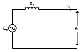
When the generator is connected to an open-circuit transmission line, the line draws a charging current, therefore Vt > Eg.
But, when the generator is disconnected from the line, no charging current is delivered by the generator, i.e.,
Ic = 0 ⇒ Vt = Eg.
So, the terminal voltage decreases.
or
A long transmission line under no-load conditions behaves as the capacitive load. The effect of armature current is purely magnetization. When the alternator is disconnected, there is no magnetizing effect. So the terminal voltage decreases with the same field current.
Ques 99. A field excitation of 20 A in certain alternator results in an armature current of 400 A in a short circuit and a terminal voltage of 2000 V on an open circuit. The magnitude of the internal voltage drop within the machine at a load current of 200 A is
1 V
10 V
100 V
1000 V
Answer D.1000V
Explanation:-
Given
field excitation If = 20 A Short circuit armature current Isc = 400 A Open circuit terminal voltage Voc = 2000 V Load current IL = 200 A
Generated voltage per phase of an alternator is given as
Ef = Vt + ILRa + ILXL
If the armature resistance is neglected than Generated voltage
Ef = VPH + ILXL
For a given field current, under short circuit condition
Ia = Isc; Vt = 0
∴ XL = Ef ⁄ Isc————–(1)
For open circuit
Ef = Voc ; Ia = 0
Putting the value of Ef in equation 1 we get
XL = Voc ⁄ Isc
= 2000 ⁄ 400 = 5Ω
Hence Internal Voltage Drop = Ia × XL
= 200 × 5
= 1000 V
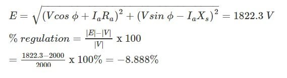
Ques 100. A three-phase alternator has a negligible stator resistance. A short-circuit test is conducted on this alternator. At a particular speed, a field current is required to drive the rated armature current. If the speed of the alternator is reduced by half, the field current required to maintain the rated armature current
− 8.9%
14%.
0%.
7%.
Answer 1. − 8.9%
Explanation:-
No Load Induced Voltage of Alternator “E” is given as
FOR TRANSMISSION AND DISTRIBUTION SYSTEM MCQ CLICK HERE